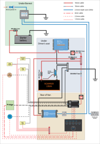
Electrical wiring diagram - what have I missed / done wrong?

SteMacK

New Member
VIP Member
Electrical wiring diagram - what have I missed / done wrong?

Trying to design the electrics for my van and have got this so far. I'm reasonably confident I've selected all the right parts I want in the system, but having never done this kind of thing before I've no doubt not thought of something.

One thing I'm not sure about is if there is enough space to run the 3 large cables through from under the bonnet to the van interior?

Would be good to get your thoughts, cheers.
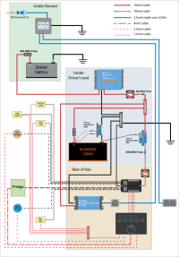

Wiring_diagram_v001_03.png
 
Yes, I have three cables like your drawing.
On my T6.1 there is a fusebox on top of the battery, which has several spare connections you can go directly onto.
 
Would be good to get your thoughts, cheers.

Looks pretty good!

I would fuse the feed from EHU charger to pos bus bar on bus bar side, especially as it goes rear -> under seat. Remember electricity travels both ways so a wire fault could ground your main positive bus bar. Sure, you have a leisure battery main fuse as an ultimate protection, but the main fuse and wire thickness is probably generous compared to charging wire.

Edit: just saw the wire thicknesses - ok same thickness for LB pos and EHU pos. Still, main fuse is likely larger than max charging current and if you have to burn a fuse on the road you might want to burn a lesser one than the main one that cuts all of your leisure electrics ;)
 
Last edited:
I've updated this with that change (and a couple of others after reading some of the Victron instruction manuals about fuse sizing etc.

Wiring_diagram_v001_03.png
 
Looking good. A couple of comments:

I’d fit a larger fuse in the LB pos to avoid nuisance trips. Make it bigger than max load and smaller than cable capacity. 100a would probably be fine.

Consider an isolator after the LB main fuse to allow you to totally isolate the LB.

Why the isolator on the DC-DC output? If you want to control when it charges you can put a switch on the small cable on the green plug on the Orion (see the instruction book). I have this as I don’t want the LB charged every time I start the van.

Consider fitting cables for a future solar upgrade while you are doing the work. You may not want it right now but you never know in the future. Solar is an absolute game changer, especially with lifepo4.

Consider fitting an Ablemail AMT12-2 to keep the starter battery topped up from the LB. They are tiny and would fit next to the DC-DC. Useful if you don’t drive it often and/or while camping.

I’d recommend a fused busbar for the positive busbar under the seat. Smaller and neater than a separate busbar and fuses.

If you used a Victron ip65/67 smart mains charger (rather than ip22) you could put this under the bonnet as well and save space in the van and shorten cable runs.
 
I’d fit a larger fuse in the LB pos to avoid nuisance trips. Make it bigger than max load and smaller than cable capacity. 100a would probably be fine.
Makes sense, will do that then.

Consider an isolator after the LB main fuse to allow you to totally isolate the LB.
Yes

Why the isolator on the DC-DC output? If you want to control when it charges you can put a switch on the small cable on the green plug on the Orion (see the instruction book). I have this as I don’t want the LB charged every time I start the van.
Didn't realise you could do this, will need to read the instructions a bit more!

Consider fitting cables for a future solar upgrade while you are doing the work. You may not want it right now but you never know in the future. Solar is an absolute game changer, especially with lifepo4.
I had thought about that, but trying to save as much money as I can doing this and really not sure I would ever need solar the way I am likely to be using the van.

Consider fitting an Ablemail AMT12-2
Will have a look into this.

I’d recommend a fused busbar
Good idea, I'll definitely be doing this.

Victron ip65/67 smart mains charger
I had thought about that, but wasn't sure that I could fit it and a weather rated socket into the space along with everything else. Need to have a proper look into it.


Cheers for all the advice. Have given me a few more things to think about now!
 
I had thought about that, but trying to save as much money as I can doing this and really not sure I would ever need solar the way I am likely to be using the van.
It wouldn’t take much. Up the size of the positive cable from under the seat to the back of the van to 16mm2 and have a point accessible in the rear for a negative cable. The larger cable will help reduce any voltage drop and increase capacity so the solar controller could be put in the rear of the van. The rest (panel, cables from panel and MPPT) can be done when/if you go that route.

I had thought about that, but wasn't sure that I could fit it and a weather rated socket into the space along with everything else. Need to have a proper look into it.
You could cut the plug off and wire direct into the consumer unit and use the breaker as a switch. No need for a separate socket then.
 
Up the size of the positive cable from under the seat to the back of the van to 16mm2
Would I not need another separate cable from the 12v supply to the fuse box? Easy enough to add in another cable though.

Having a look into using an ip65 charger in the engine bay somewhere (possibly under the scuttle). But trying to work out how to run a cable from it to under the driver's seat. Not sure how to keep the weather rating but extend the cable? I guess I would just cut the red eyelet off the end of this and extend it with some kind of ip65 rated connector?
If you buy the ip65 rated charger then it comes with a quick plug so you can then plug in a Victron extension cable without chopping off any cable ends.
Assuming it’s something like this one.
You can add this
 
You can add this
The problem I have is that I won't be able to fit the bulky cable connector through the grommet between the engine bay and the passenger footwell. I would need to cut a much bigger hole and somehow seal and protect the edges from rubbing on the wire.
 
Would I not need another separate cable from the 12v supply to the fuse box? Easy enough to add in another cable though.
Not sure what you mean by the 12v supply. Sorry, been a long day! If you mean from under the seat to the rear of the van then no. You just need a single, suitable capacity, positive between front and rear. The negative goes via the chassis.

Just noticed on your diagram you have negatives running front to back. There is no need for these as you can use the chassis (as VW does for the whole vehicle). There is an internal ground point in the rear corners inline with the rear lights and one under each front seat inline with the centre mounts. Also, there is no need for a battery protect with a lifepo4 that has a BMS.

Having a look into using an ip65 charger in the engine bay somewhere (possibly under the scuttle). But trying to work out how to run a cable from it to under the driver's seat. Not sure how to keep the weather rating but extend the cable? I guess I would just cut the red eyelet off the end of this and extend it with some kind of ip65 rated connector?
Use the supplied ring connector with the negative connected to a ground point under the bonnet. Cut the positive on the supplied ring connector near the plug, and join a new section of cable via a midi fuse and feed through the bulkhead to the positive (fused) busbar under the drivers seat. There is a ground point in the scuttle - look through the plastic slats and you will see it inline with the starter battery negative. Or use one of the headlight bolts on the near side of the battery. Pics below:

IMG_1021.jpeg

IMG_1020.jpeg
 
Back
Top