You are using an out of date browser. It may not display this or other websites correctly.
You should upgrade or use an alternative browser.
You should upgrade or use an alternative browser.
Epic-Rob’s Lithium Leisure Build Thread
- Thread starter Grim Reaper
- Start date
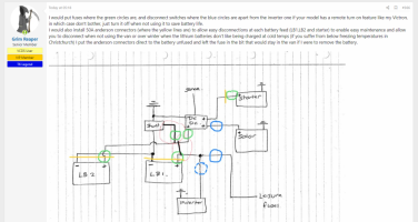
I would put fuses where the green circles are, and disconnect switches where the blue circles are apart from the inverter one if your model has a remote turn on feature like my Victron, in which case don't bother, just turn it off when not using it to save battery life.
I would also install 50A anderson connectors (where the yellow lines are) to allow easy disconnections at each battery feed (LB1,LB2 and starter) to enable easy maintenance and allow you to disconnect when not using the van or over winter when the lithium batteries don’t like being charged at cold temps (if you suffer from below freezing temperatures in Christchurch) I put the anderson connectors direct to the battery unfused and left the fuse in the bit that would stay in the van if I were to remove the battery.
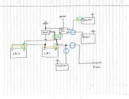
I would also install 50A anderson connectors (where the yellow lines are) to allow easy disconnections at each battery feed (LB1,LB2 and starter) to enable easy maintenance and allow you to disconnect when not using the van or over winter when the lithium batteries don’t like being charged at cold temps (if you suffer from below freezing temperatures in Christchurch) I put the anderson connectors direct to the battery unfused and left the fuse in the bit that would stay in the van if I were to remove the battery.

Last edited:
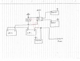
Ah yes that was just my mistake - its only a small wire with a 3amp fuse on the shunt and i have a 100A cable connecting the 2 pos terms together fused at either end
and yes i have got the fuses in about those spots and at the mo just one disconnect switch to leisure fuses (thats the switch you can see on side of seat base)
so from the DCDC charger with your diagram you are effectively charging to both LB at the same time? i always thought it was the way to put the charge into one and the load out of the other so as to keep batteries balanced.
I have taken the DCDC feed to + on LB2 and taken the load of the + on LB1. but i guess as the pos are connected together both batteries are receiving charge .
But it still leaves me wondering how the flow through the batteries is working
but that just gets me thinking is LB2 sat on its own at the end? because the neg and pos terminals are connected and the feed out is from LB1 will even power be put into both batteries?
How i had it before with the earth coming off LB2, whilst it defeated the shunt it gave a power flow through of both batteries.
How To: Connect two batteries in parallel – Part 2 2nd to last diagram
PS it does occasionaly get to freezing - but not today as its been about 26 deg
If you were to bring the pos and neg feeds from both LB1 & LB2 to a couple of busbars and then connect to the DC charger and shunt there, that would be fine, it's not so much about keeping cables same length as keeping them as short as possible, and with 16mm2 cable over a distance under a metre you're not getting much resistance difference.
You only get a current flow through BOTH batteries if they are connected in series. Parallel connections use the cables to each battery, and it's more about resistance than where you connect to.
Don't leave the inverter connected if it doesn't have an off switch, it will drain your batteries.
You only get a current flow through BOTH batteries if they are connected in series. Parallel connections use the cables to each battery, and it's more about resistance than where you connect to.
Don't leave the inverter connected if it doesn't have an off switch, it will drain your batteries.
If your lithium batteries have a built in BMS (which they probably have) once one battery is full it will refuse charge and the other one will top off if there is any difference
some observations:
.
A- this looks fine, but I've had issues with this style of breaker switches getting hot causing volt drop when pulling current - so keep an eye on it . . . if it starts to get hot swap out for a MIDI or MEGA fuse.

.
B- is this the main chassis ground connection in yellow? - of so the green? should be both the LB1 + LB2 NEG feeds.

both battery NEGS need to got to the SHUNT, then one common GROUND from the SHUNT to the van BODY. Also the gauge of the cable needs to be the same thickness as the main POS as it will be carrying the same high current . . . so if you use 150A cable for the POS, then you need 150A cable for the NEG . . .
if 2x 150A POS then you need 1x300A for the main NEG from the shunt ( same as you have done with the main starter battery feed)
..
C - where is the second battery? - each battery needs a fuse next to the POS interlink cable.

...
D - Fuse should be on the POS side of the battery. (technically it could go on the NEG side, but depending on the circuit layout the power could fin an alternate route to ground so POS is always best place)

.
E - the second LB2 should have a direct connection to the shunt, it can go to either the LB1 or the shunt, whatever is shortest.
yellow or blue is ok, red is not right, the shunt will not read the power correctly.

F - where is this master switch in your schematic?

.
G - can you post a pic of your starter battery NEG terminal and connections
H - Inverter NEG connection needs to do direct to chassis ground, same as all you loads NEGS to chassis. . . ONLY the LB1 & LB2 NEGS to shunt - then shunt to chassis. credis to @Grim Reaper for spotting that one.

I - Fuse layout - this is where the fuses would normally be, as close to the battery POS connections as possible.

J -
.
A- this looks fine, but I've had issues with this style of breaker switches getting hot causing volt drop when pulling current - so keep an eye on it . . . if it starts to get hot swap out for a MIDI or MEGA fuse.
.
B- is this the main chassis ground connection in yellow? - of so the green? should be both the LB1 + LB2 NEG feeds.
both battery NEGS need to got to the SHUNT, then one common GROUND from the SHUNT to the van BODY. Also the gauge of the cable needs to be the same thickness as the main POS as it will be carrying the same high current . . . so if you use 150A cable for the POS, then you need 150A cable for the NEG . . .
if 2x 150A POS then you need 1x300A for the main NEG from the shunt ( same as you have done with the main starter battery feed)
..
C - where is the second battery? - each battery needs a fuse next to the POS interlink cable.
...
D - Fuse should be on the POS side of the battery. (technically it could go on the NEG side, but depending on the circuit layout the power could fin an alternate route to ground so POS is always best place)
.
E - the second LB2 should have a direct connection to the shunt, it can go to either the LB1 or the shunt, whatever is shortest.
yellow or blue is ok, red is not right, the shunt will not read the power correctly.
F - where is this master switch in your schematic?
.
G - can you post a pic of your starter battery NEG terminal and connections
H - Inverter NEG connection needs to do direct to chassis ground, same as all you loads NEGS to chassis. . . ONLY the LB1 & LB2 NEGS to shunt - then shunt to chassis. credis to @Grim Reaper for spotting that one.
I - Fuse layout - this is where the fuses would normally be, as close to the battery POS connections as possible.
J -
I think we are good! well in the sence that everything is working..... have followed yours and Grimreapers diagrams so i am just hoping its doing all its voodo electricky stuff 
my 350w inverter seems to have zero draw when switched on, worried me a little but then i plugged a soldering iron in to test and got 2.7amp draw on shunt.
shunt also shows charging when engine is running at around 29amp and solar charging at a measly 0.3amp.
SO all i have to hope now is when it goes back to dealers on 18th to get all the error codes (ACC, hill start, F+r parking sensors etc) cleared it all works out.
Thanks for the help guys
Cool... Post some more pics of your van and your build.
This is your thread now.
So you can post anything you like.
This is your thread now.
So you can post anything you like.
great, post some more pics of the leisure setup too.
and any solar you have.
we like pictures.
and any solar you have.
we like pictures.
well leisure setup doesn't really look any diff to the pics above.
battery under each seat and a jumble of wires.
not much to see with solar.
i have a 160 flexi panel stuck to poptop. and the cable routed behind the wall board poping out just behind drivers sest.
but over next few weeks i will post all build pics i took ans bit of an explanation of
'how i done it' i can say there has easily been 200hrs involved and probly £15k of conversion parts on top of van price of about £35k.
i have done 4 now over last 3 yr starting with a cheap 2010 swb through to a new 6.1 with plenty of extras.
would i do another? not in a hurry.
Happy to have been some help.
Bit of a problem ….
So this seems to have been happening over a number of weeks now.
I had a few instances of my van (starter) battery going flat if I hadn’t used van for 4ish days, a bit of a mystery but I put it down to the dashcam which is on 24/7, so i disconected to test, but not sure if it is that,
Also a few weeks back my leisure batteries completely discharged (2x 100Ah lithiums) so I recharged them in situe in the van, they were connected together so I just put charger on one battery and got them both up to about 13.5v where they seemed to stick. When I connected them back into van I did only get 75% soc (state of charge) on the shunt meter whereas before I would get 100%soc.
Anyway this happened again today after a weekend away, they got down to about 50% soc then shut down. When I got them out this eve they were both on about 11.5V
So I have a DcDc charger so thought I had better check its all good with fuses etc cos there should be no reason for the batteries to go flat with a dcdc charger and solar setup, only had the 12v fridge on.
All the fuses are good and I tested wires with multi meter. So testing with multi meter at the dcdc charger inputs I seem to be getting about 22v off the solar panel and 14.5v out of alternator (12v when engine off) and I also tested the wire that would go to + on the leisure battery and there is feed coming out of that.
So that begs the question why are my LB not charging????
I am also wondering if the cause of my van battery going flat is a draw through the dcdc charger into LB but would think the dcdc charger wouldn’t allow this??
So any thoughts?
Inverter always on? Fridge always on?
What does the battery monitor say regarding drain on the batteries when you think everything is off?
What battery monitor are you using? Victron BMV? Set to correct type for Lithium? The Victron resets the SOC to 100% when the voltage has reached and maintained a set voltage for a period of time so as long as the batteries have had enough time to get to that stage the SOC should always be realistic for that period of discharge, however if the re-charge current (off the solar or van alternator) never gets to the point the SOC resets the figure can be off by some margin.
Do you have the inverter and the fridge earths the other side of the shunt or are they attached directly to the batteries?
Last edited:
Similar threads
- Replies
- 5
- Views
- 442
- Locked
- Replies
- 12
- Views
- 1K

