Hello
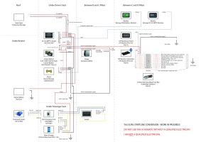
I'm enjoying designing the electrical system for my second conversion. I know my limitations and so will my insurance company, and want to find an automotive / conversion electrician in York / Yorkshire / North East area who would be willing to check over my design, then certify it once I've installed it - of course I recognise this would be a paid service. I want to do as much of the work myself as possible so that I understand the beast when out in the field and something doesn't behave as expected. I don't mind driving the vehicle within Yorks / North East to have it certified and assume the assistance with design would be done by email. I include the schematic to date - if anyone on the forum has any observations to make on their experience with Transporters, then please do comment - it would be much appreciated.
I can't afford a lithium battery yet (dogs, kids, etc) but have designed the system around one in the future, hopefully just being a straight battery swap. I'm thinking Renogy, so have gone with their charger. The RJ45 cable that runs from drivers seat to the rear can be repurposed for the smart monitoring of that battery and the charger via the addition of the hub and BT2 later on.
Big thanks to @Deaky and @Dellmassive whose posts I've really benefited from on this topic.
If you are the electrician I'm looking for, please post or PM me.
Many thanks


