Hi all, lone time lurker, first time poster.
I need to be able to remotely trigger the horn on my T6, and I'm struggling to work out how to simulate the horn being pressed.
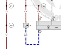
I've downloaded the "Circuit_Diagrams_Basic_Equipment_T6F", and am looking at page 10. I was hoping I could short the two horn wires to trigger the horn. These are connected to T41/12 (br) and T41/11 (br/ge) on the 41-pin connector, grey (T41).
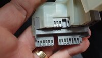
Unfortunately looking at the connector, there is no pin populated in position 11 of the connector! Can anyone help me with the two pins the need to be shorted to get the horn to go? (see attached photo, pins increment from left to right)
I suspect my issue is that I have a "multifunction steering wheel", while the circuit diagram specifies "Only models with no multifunction steering wheel". (See attached photo of steering wheel).
Thanks very much


