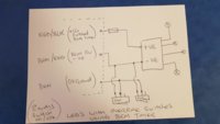
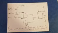
Just had another look and i see what you are trying to do. . . . . . looks ok to me now.
things to note,
Both your switches will need to be set to the same state all the time, (if you go for two switches)
you could fit an additional small fuse at the start of the +12V feed if you felt the need to,
using your 3way switch above it will be (on/off/on type switch)
I = BCM control, extra leds will come on/off with doors open etc
0 = extra leds will be OFF
II= extra leds will be ON (BCM -ve override unitll the BCM +12v timeout kicks in)
***************************************************************************************
Factory Non-LED 3 wire setup:
(brown) - earth point left a-pilar
(brown/red) - connection 1 main harness (BCM switched neg 0v)
(red/black) - positive connection 1 main harness (BCM timed +12v) ( 7.5A fuse 24 holder C)
****************************************************************************************
I drew a couple of rough sketches and realized they were the same as yours anyway. (one with a 2way switch and one with a 3way switch)


