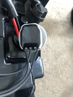
Haha here he goes.Watch this space.
I looked at these. I reckon a long strip similar to @Robert ‘s tail lamps indicators, but doubled-up so that the second strip faces backwards thus illuminating the cluster would sufficiently illuminate it
Haha here he goes.Watch this space.
OEM T6 rear LED lights are factory equipped with 16W filament bulb for indicator.
My LED sequential strip take 0.33A, which translates to 4W.
This is obviously short by 12W to expected 16W and results with hyperflash and double frequency click in the instrument cluster.
Available coding adjustment for indicator setup is as follows
BCM 09, Byte 18
bit 3&4 = front/rear/side
00 = 21/21/5 W
01 = 21/27/5 W
10 = 21/16/5 W
11 = 27/27/5 W
The lowest possible setting is "10" which I had already as a factory setup so the only solution was to add extra resistor.
Quick maths
Required indicator additional power(wattage) = 16W - 4W = 12W
P = U x I ---> I = P / U = 12W / 12V = 1A ===> R = U / I = 12V / 1A = 12Ω
So the selected resistor was 12Ω and for sufficient heat dissipation 50W seems to be sufficient.
RS PRO Panel Mount Resistor
Credit to @Loz for resistor type and resistor layout inspiration.


Extra resistor has to be added parallel to the LED stripe and not in series. Obviously resistor value (ohm) should be calculated based on the wattage of your LED stripe.I have not started this project yet, so i was just going to get my multimeter on the pins and work out which one had voltage when the indicators are flashing. You only need to add the resistor in-line on the positive led. Where did you get the blue wedge connectors from and do they fit into the bulb holder ok?
I don't remember mate.@Robert just a quick one - my resistors have arrived and I just want to check I’m splicing the correct wires.
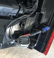
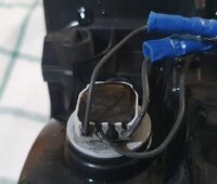
Is it the two that are beside each other (wires 1 and 2, with 4 being left alone)?
View attachment 67872
That’s what it appears to be, but your image resolution has been downsized.
View attachment 67871
(I’ve soldered the LEDs to male wedge connectors)
They were an eBay purchase and fit the holders fine. They took 17 days to arrive.Where did you get the blue wedge connectors from and do they fit into the bulb holder ok?
Sorry you are right, my mistake. The resistor needs to be across the load (led strip) to increase the resistance. I will know more once all my bits arrive...Extra resistor has to be added parallel to the LED stripe and not in series. Obviously resistor value (ohm) should be calculated based on the wattage of your LED stripe.
@Robert just a quick one - my resistors have arrived and I just want to check I’m splicing the correct wires.
Is it the two that are beside each other (wires 1 and 2, with 4 being left alone)?
View attachment 67872
That’s what it appears to be, but your image resolution has been downsized.
View attachment 67871
(I’ve soldered the LEDs to male wedge connectors)

 .
.


 ).
).
No need for an apology.
We are not trying to increase the resistance but actually to reduce it.Sorry you are right, my mistake. The resistor needs to be across the load (led strip) to increase the resistance. I will know more once all my bits arrive...
Has this happened to you? Do you know where these LEDs were installed?Yes, indeed sometimes the PWM can induce LEDs having a regulator "onboard" to misbehave....
View attachment 68310
Yes, those were mine. I had them in a T6 in cargo room roof lamps (replacing the regular bulbs). After a few weeks the smoke came out.Has this happened to you? Do you know where these LEDs were installed?

Seems like the safer option to turn it off, would it have an effect on anything else? Can you recommend a resistor as well please as I've fitted LED indicator bulbs in the rear, they work perfectly but i have fast flash on the dash!
Cheers for that, im going to have to read it a few time as i dont understand the equation part at the moment!You need to perform some calculations/measurements to select correct ones.
Have a read below.
EDIT:
There is no side effects whatsoever when PWM is deactivated on indicators.
