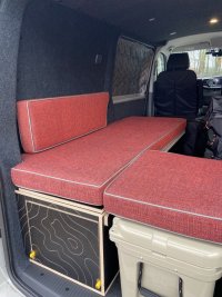
Off-side cable routing from drivers seat base to back quarter panel - help please

RobFlynn

Senior Member
VIP Member
T6 Pro
I need to get cables from under drivers seat to the o/s rear quarter area - the upper half between C and D pillars. I can get to the bottom half from the O/S passenger panel then via the C pillar. There is then no route up into the upper area I need.

Do I have to go right the way back, into the D pillar and then out of there, or is there a better route? I want to get to areas A and B in the photo. Note: I pinched the picture (best I could fine) and it’s of a N/S. I need to reach the same positions marked but on the O/S of a single slider. Thanks

IMG_2524.jpeg
 
Ooo - nice job 👌 so is that some from the C pillar, along the middle and back, and then some along the roof and down the D pillar? If so, is up the B pillar, along the roof to D pillar the better option?
 
Ooo - nice job 👌 so is that some from the C pillar, along the middle and back, and then some along the roof and down the D pillar? If so, is up the B pillar, along the roof to D pillar the better option?
I had to split my cables so the heavy positive goes at low level and the solar cables go high level. Low level is easier, marginally.
 
Mine is basically power from battery in at the lower, onwards distribution goes to the upper route.
 
That’s the neatest job I’ve seen so far. I do not thank you for causing me more work 🤣

What diameter is that grey conduit?

How do you intend to access all those fuses once the panels are on?
 
Last edited:
Thank you. I was working on the principle that if it’s neat, it’s easy to fault find.

That panel uses the screw insert thingys rather than Christmas tree fixings so it’s very easy to remove.

A few years in, it is conforming to Sod’s Law : because I made it easy to access, I haven’t needed to go behind it because everything works perfectly. :D
Grey conduit is 20mm from memory.
 
Does that 20mm conduit run all the way from battery - IE. Does it fit all apertures and manage bends through B and D pillars?

Sorry for all the questions. My Kombi is my daily and I have kids. I need to figure out as much as possible as I can’t be pulling it apart to investigate only to put back together without getting anything done.
 
It goes all the way except for about 2”-3” where it passes around the back of, then through the D pillar. Probably a bit over cautious most of the way but necessary when passing near exposed edges so I don’t have to worry about it rubbing.
 
Happy to send some pics over of the route if that would help. Mine was our only vehicle when I did it and our lad was very young so I totally understand your predicament - 95% planning, 5% execution.
 
Any more pictures massively appreciated. You’ve been a lot of help already :)
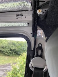
The seatbelt is hiding the hole, but you can just see the edge of it in the red circle.

I can’t now remember if it comes out in front of or behind the panel marked with an arrow. If you poke something through it’ll become clear.

Bear in mind - please do read up on cable safety in vehicles - for example by using grommets, the two types of cable sheathing available (and when to use each) and the importance of using flexi conduit in some circumstances. I’m not an auto electrician.

IMG_8798.jpeg

IMG_8797.jpeg
 
Is all that lot for leisure electrics in a camper conversion?
I won't be showing my install as it's a bit/lot more rough around the edges :whistle: due, in part, to there being windows all round including behind the wardrobe, plus I am rough.🤠
 
Is all that lot for leisure electrics in a camper conversion?
I won't be showing my install as it's a bit/lot more rough around the edges :whistle: due, in part, to there being windows all round including behind the wardrobe, plus I am rough.🤠
Yes. 10 channels:

6 lighting circuits
USB sockets
Mini amp power
Couple spare
 
I used one of them mini blade fuseboards under the driver's seat alongside the Roamer but in all fairness that's just for the Waeco fridge and Webasto supplies, the converter Redline had put a Sargent ec160 in the wardrobe for 12Vdc and 230Vac EHU circuits including the Roamers Victron 12/30 charger.
As I say it's a bit rustic and luckily hidden from view. :geek:
 
  • Like
Reactions: CJW
When I did mine, I did run some cables from passenger side to rear to EXACTLY the location you want, for a light switch for my site/day van. But..... I've also fed cables from drivers side to the roof so I do know the route. (Pics below to help). Apologies in advance if some of this you know or have done, it's just 'what I did'.
1. Depending on your requirement you may have to take out drivers seat, you then have access to floor, wiring beneath and bottom of B pillar On drivers side. Pop off the 'B' Pillar trim by drivers door. This will reveal OEM loom going up to roof.
2. Using loom tape, fully wrap your wires for length of rise to get to ceiling. This helps protect and keeps everything neat. Cable tie your new loom to existing loom behind trim.
3. Cable tie one or two lengths of flexi-con to the strengthening rib running across the roof above head rests, and feed cables across to passenger side. See photo 1 with two flexi-cons as I put in a spare to future proof. You can see my additional loom taped to OEM loom so it looks original. In photo 2 you can see the flexi-con over the route. Don't worry though you can affix to the rear of the strengthening rib too, so you don't need to take out the cabin headliner, just the load roof liner which is MUCH easier!!
4. Partially wrap cables to look like OEM loom and you can tape these to the existing loom all the way to tailgate C Pillar. See photo 3. Hard to see, but my cables are sat on top of this.
5. Run a flexi-con down the C Pillar cavity from roof to the middle of the van below the top panels. See photo 4 for route in red. (From recall, you may?? not need to feed a flexi-con down the C pillar cavity but I did as I found it easier to route wires. You may?? be able just to poke them down, but I wanted to ensure they did not rub or chaffe in the blind cavity). For your needs you will need 1 length for the drop down the C Pillar. One length from C pillar to first point of utilisation, 1 length to complete to second point of utilisation. This will allow you to feed cables and get to your terminations. I cable tied flexi-con to the holes along the route as required.
6. Drill two holes on the centre brace in middle of van, insert a small cable grommet to protect wires and feed up tails to where you need them. (sorry don't have a photo of this)
7. As said above, good practice to use edge strip where abrasion may occur as cables pass over obstructions. See photo 5 for example
8. You can see where my switch is sited on photo 6, just to prove thats where I ended up, as you intend.

Caveat to say that as others have posted there is more than one way to do this, but this is how I did it.

HTH?

Cheers.

Edit to say, that once the two flexi-cons are above the front seats and roof liner back, you only have to whip off the B pillar trim to feed wires across the van from driver to passenger if required in the future without faffing around with the seats etc.
IMG_0696.jpeg

IMG_0691.jpeg

IMG_9102.jpeg

90D53119-16F8-421B-ABA7-2A3F96226F22_1_105_c.jpeg

IMG_9212.jpeg

IMG_1551.jpeg
 
Back
Top