2023 shuttle not starting - Help with VCDS

Jvcarrier

New Member
VIP Member
I have an issue with 2023 shuttle not starting and some electronics not working (windows, dash etc) the hazards, blower, side doors wipers etc work fine,
It is being striped of disabled driving gear so I could have disturbed a connection, but all wiring seems to be back to factory and it was all working until the
last few bits were taken out. I got a bit complacent and did not photograph the changes.

There seemed to be a none o/e brake switch bracket in front of the brake pedal? I still have not found the electric handbrake switch plus what does "engine
start blocked by immobiliser" imply? - it was starting fine.

I have run a VCDS test but I am unable to understand what the details are pointing to. I have attached the the engine/trans the instrument cluster report just says "cannot be reached"
as hopefully the main culprits.

I would appreciate any views on what I should be looking for.

Regards

John
 

Attachments

  • vcds.pdf
    1.6 MB · Views: 6
I had an issue when stripping out the mass of modifications on a wav. Turns out I'd managed to disturb a poorly re made connection in the canbus wiring high up behind the pedal box . Sorted by @Dav-Tec .
I've retained the electric hand brake on the dash so I can swivel the front seat !
 
Hi, full scan report attached.
Front is striped down so errors on lights distance sensors etc expected, interior is also striped out ready for pop up roof. Most of the lights inside I have put back to try and reduce fault codes.
A couple of questions, if I may.

Does "lost (or no) communication with instrument panel cluster for example imply - a can fault or an electrical fault?
What does Engine start blocked by immobiliser and what do the A-Sia B-Sia values imply
On the Transmission control unit what does Gang_R mean (selector is in park and p illuminated.
On last page (33) it gives Vign as 0.0v is this significant.

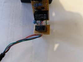
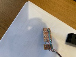
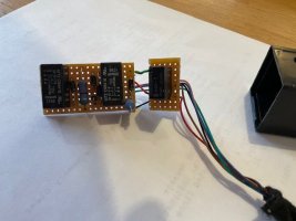
Most of the equipment taken out was clear as to purpose,IMG_4933.jpgIMG_4930.jpgIMG_4931.jpgIMG_4932.jpg one about flasher size unit was not identifiable and looks bespoke, any ideas appreciated.


regards

John
 

Attachments

  • Full VCDS.pdf
    7.8 MB · Views: 5
  • Wow
Reactions: mmi
It looks like a CAN cable damage somewhere behind the cluster (is a CAN node in the bundle that spreads to most modules).
 
On last page (33) it gives Vign as 0.0v is this significant.
Could be fairly significant as OBD socket pin IGN_ON is powered from fuse SC40 which also supplies power to the following:
Mirror adjustment switch -E43-​
Headlight range control regulator -E102-​
Rear fresh air blower switch -E179-​
Centre switch module in dash panel -EX22-​
Oil level and oil temperature sender -G266-​
Pressure sender for refrigerant circuit -G805-​
Parking aid control unit -J446-​
Coolant shut-off valve relay -J541-​
Climatronic coolant shut-off valve -N422-​
Voltage supply relay 2 -J710-​
Front left headlight -MX1-​
Front right headlight -MX2-​
Diagnostic connection -U31-​
Left washer jet heater element -Z20-​
Right washer jet heater element -Z21-​
A couple of those seen as offline in the scan.​


Slightly off topic - it's model year 24 = "R" in the VIN​
1736007246605.png
Impressive mileage, too!​
 
Thanks for responses. I think the issue is a duff instrument panel. I disconnected it and the fault codes remain the same thus I concluded it is not working. There is power + and - to the connector. Will replace and keep fingers crossed.
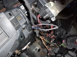
Have a twisted pair joined by a resistor (blue and red plus a grey and red) unaccounted for close to the steering column. Can anybody help identify what is missing.

IMG_4909.jpeg
 
The integrated circuit in the photos is 3 relays and some zener diodes and resistors, it's hard to say what it's for, you'd have to provide a detailed description of where it was connected in the car.
 
Have a twisted pair joined by a resistor (blue and red plus a grey and red) unaccounted for close to the steering column. Can anybody help identify what is missing.

Don't know what's missing but twisted pair and resistor sounds like CAN bus termination - the resistor is added in lieu of some CAN module to keep the bus happy
 
Thanks guys, guess it’s back to paging through the current flow diagrams. I agree it’s almost certainly a couple of CAN wires but for what? Anybody managed to search the diagrams by wire colours?
 
I remapped the entire engine installation from T5 to T6 according to the diagrams and wire colors, I found no errors or changes, everything worked 100%. I don't know how it looks in T6.1, I don't have diagrams (for now it's beyond my scope of interests, because I don't have such a car and I'm not in the automotive industry, I do everything as an amateur).Everything should be clear, except for additional installations, for example a non-factory anti-theft system, etc. And this may be a problem, because the dealer orders this at the customer's request and it is not shown on any diagrams.
 
Has the key start been altered on your wav? I remember on mine the key wasn't put in the column switch but into a cup on the dash where a "sensor ring" which normally sits around the steering column barrel had been re located. They could be the two wires if so.
Mine also had two buttons on the dash and a large box of relays behind the dash to replace the key turning function
 
Back
Top