Alternator Upgrade

parts have started to arrive for the next challenge.......

2x 4 AWG kits and 2x 8 AWG kits

20180711_132226.jpg

the 2x amps are:

Kenwood KAC-X4D (bridged 4ch giving 2x300w rms for front mids and tops )

Maximum power output 1200W

Rated power output (4Ω) 120W x 4 (4Ω)

Rated power output 150W x 4 (2Ω)

Bridged power output (4Ω) 300W x 2


and

Kenwood KAC-X1D (monoblock on 2ohm 700w rms )

Maximum power output (4Ω) 1600W x 1

Rated power output (4Ω, 14,4V) 600W x 1 (20Hz ~ 200Hz, 1%THD)

Rated power output (2Ω, 14,4V) 700W x 1 (100Hz, 1%THD)

Rated power output (CEA-2006) 600Watts RMS x 1 at 4 ohms and 1% THD


and the sub: boxed 15" L7 Solo-Baric L7S 15 Inch Subwoofer | KICKER®
 
Very very nice, no shortage of juice then :)

Where are you planning on fitting your 15 inch? My 10 inch is being drowned out by the fronts and if I turn the fronts down to match then I can’t hear anyone on the hands free :( which is just a bit of an issue!

It’s a right pain but im going to have to redo my sub enclosure (thanks goodness I tried my old sub) and go for at least a 12 inch now
 
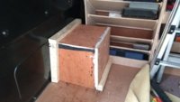
15" kicker sub is directly behind the drivers seat facing forwards at floor level.

its about 20mm back from the bulkhead so rattles the hell out of it. . . . on the last install i cut 4x 150mm holes infront of the box to allow sound into the cab.

but i think on this build ill cut a big square out in front of the box....

and adding the second amp to run the mids/tops helps balance out the power levels with the amped sub.
 
Don't suppose you have a pic? :)

Try putting sound deading on the bulkhead as I'm not getting any vibration on mine, granted a 10 inch cant compare to a 15 inch :laugh:

Managed to redo the boxing and I can now just squeeze in a 12w6, the 10 inch will have to go back in for now, but at least I'm ready for it. going to be a right pain though in 7 to 10 years time when I change the van 3.5 tubes of stix all have gone into that box!
 
Well the good news is that the new box and sub is in :)
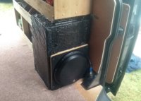
The bad news is that I've had to remove the soundproofing from the bulkhead (used the little that came off clean to wrap the sub box). Worse though is the fact that I'm going to have to fit a leisure battery and in all likelihood add another sub :( as it just isn't loud enough. I'm also finding that whilst the van can provide enough power, the sub amp needs its own feed to the battery or the other amps get starved of power (I think that is what is happening), mains drop in volume at times when the sub is also going. If I need to run a new cable then I might as well make it to power/charge the 2nd battery, otherwise it will be something like 10 metres long

IMG_20180721_163942226_HDR (2).jpg
 
Fascinating! If I understood correctly you are feeding your amplifiers with AWG 0 cable from starter battery and the return path (ground) is van’s chassis. Or, even another AWG 0 cable from starter battery grounding to amplifier grounding point (to reduce chassis resistance)?
 
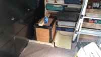
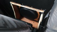
Well according to the lovely people of a certain forum, my sub placement is about as bad as you can get! Anyhow sub moved to a new tempory place. Turns out that I have no choice but to cut a hole through the bulkhead if I want it to work.
IMG_20180722_174044517.jpg
Fascinating! If I understood correctly you are feeding your amplifiers with AWG 0 cable from starter battery and the return path (ground) is van’s chassis. Or, even another AWG 0 cable from starter battery grounding to amplifier grounding point (to reduce chassis resistance)?

0 gauge is being fed to a splitter fuse block, then 4 AWG is run to each amp. The return path is grounded to the vehicle chassis via the loading lash points. The anchor points give such a low resistance that a separate return cable isn't needed.

I would like to upgrade the ground from the battery to the vehicle frame (add another cable) to help the current flow, but I'm unsure how to connect onto the battery negative clamp at this stage due to the design of it. I've been all day redoing everything, so have only glanced at it.
 
  • Like
Reactions: mmi
0 gauge is being fed to a splitter fuse block, then 4 AWG is run to each amp. The return path is grounded to the vehicle chassis via the loading lash points. The anchor points give such a low resistance that a separate return cable isn't needed.

I would like to upgrade the ground from the battery to the vehicle frame (add another cable) to help the current flow, but I'm unsure how to connect onto the battery negative clamp at this stage due to the design of it. I've been all day redoing everything, so have only glanced at it.
Thanks for the info. Got curious about resistance through the chassis to the load lashing point so had to actually try to measure. Turned out to be less than 1 mohm, so indeed having a separate return cable wouldn't really improve it. Looks like that with fat cabling you have already minimized the power feed losses below battery's internal resistance. So may be a battery upgrade at some point?
PS. The vans up here come with 92Ah main battery - so that's +20% more boost right there ;)
 
So may be a battery upgrade at some point?
PS. The vans up here come with 92Ah main battery - so that's +20% more boost right there ;)
I have already asked the VW centre about doing just that, and got a typical no you have the largest battery already 70 ah.

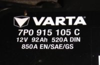
Can you take a pic of the battery details please as I would like to upgrade it to a larger one (length would be helpful to :)), so as I can get one ordered? Start/Stop rarely happens now, but I would like to have better protection for those times you turn off the engine but the radio keeps going.

Move the sub has certainly made a difference, it's not there yet so will need to cut through the bulkhead, but the amp gains are now set at a sensible level (34.6v) which is a big relief.

Thanks for double checking the lashing points resistance :) with all the playing around I've been doing, I half wondered if I had read it right!
Battery_92Ah.jpg
Length=355 mm, width=175mm, height=190mm.
 
Well my word isn't worth ... I swore I would never do this again :mad:
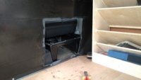
IMG_20180723_143012568.jpg

Still Mark 3 is now all done :)
IMG_20180723_180324096_LL.jpg
I went a bit off on cutting the one side :(
IMG_20180723_180313412.jpg
 
Nice...

I forgot to ask you...

How did you go about chopping the bulkhead?

What was your method?
I just used a 4 inch grinder with the thin metal cutting disk to cut out the hole. In an ideal world, I would have taken the bulkhead out, but that was just way too much of a pain, so instead I put a piece of plywood in the cab side tight against the bulkhead which was larger than the planned hole, duct tape to seal it and off I went, took longer to sort the plywood out than to cut the hole. Should have taken a bit more time on the one side though :(

You still get some dust in the cab, but nothing too bad. It was the sparks I was most worried about (or cutting to deep and catching something like the seat frame) which the plywood nicely stops. The bottom finish level I did in stages as I didn't wont to cut the bed of the van. So cut out 90% of it in one go, then as I could then see the floor levels I did another cut to lower the bottom cut height.

Then smoothed off with a file and put some metal primer paint on

Very very pleased with the results :)
 
Last edited:
Perfect.

I used a recip-saw last time with a metal blade...
 
Hi all.

This may have been asked before but I can't seem to find anything so would appreciate some help. The alternator on my t5.1 doesn't seem to be charging so needs replacing I think. Would this be a diy job or best taken to a garage where they have better facilities, i.e., ramps?
Thanks in advance for any advice.
 
It's normally a bumper off and front end moved to the service position and that gives access to the alternator.
 
Back
Top