Cab Ambient "Mood Lighting" Under-Dash - How I Done It -
This Thread continues where this one left off . . . . .
Cab Ambient Lighting (factory Mod) - How I Done It -
.....
On the previous thread we looked fitting the OEM roof light fitting, to replace it with an OEM unit with added RED LED downlights . . . . which worked out great.
Now lets look at the rest. . . . . . . . .
originally i was looking at these:
T5 T5.1 Footwell LED Lights Upgrade Kit & Trim Removal Kit

.

.
FYI there is a small 3way switch on the rear of each of the TL lights that selects the colour red/blue/white
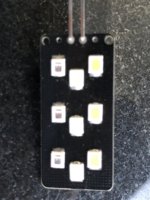
I also got a set of OEM white LED lights from the Forum Shop via @Pauly which done the same thing . . .
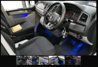
The Vans lower dash panels already had the lower light cut-outs which just needed a gentle persuasion with a Stanley blade to reveal the holes . . .
Following this guide we had the lights in . . . . picking up the Curtisey light circuit (Red/bvrown & red/black)


there was a cutout guide if needed - but it wasnt =]

.
The Curtsey light feed gave us lighting in the footwell when the door was opened at night . . . we chose the White Led units . . .

.

.

Next on the agenda was the matching Red LED ambient back-ground lighting . . . . We had seen from the previous thread that you can connect LED to the Ambient light feed (at the rear of the Light control switch) that would work the same as the rest of the dash and be dimmable . . . . as the rest of the dash.....
Now orginally i was going to cut-out a second hole in the lower dash plastics to fit a second lot of LEDs (this time Red) so that the existing would come on with the open door curtsy light in white, but then at night we could have the other LEDs red one come on . . . .
just before fitting these i come across this post on Amazon . . . .

.

They looked to do the job . . . and i wouldny need to cut the dash plastics . . . . perfect i thought. =]
They were RGB and had a remote and fancey sound/music mode - sweet.
So i ordered a few sets . . . . . .
There were two versions, 12v and USB so i grabbed one of each . . .
when they arrived a quick test showed they worked great . . .

.

one thing i did notice was that the 12v versions were brighter, but both looked the same appart from the lead . . .
one had a USB end . . . one didnt . . . . but both leads worked on both units, so effectively the units were the same, but being fed from either 12v dc or 5v dc from the USB . . . that explained why the 12v setup was brighter . . . .
Over to the van we went and connected to the same 12v ambient feed as the OEM roof light . . . . . . . . . . . . . switched on for a test . . . . . and nothing. !!!
just a dim glow, remote didnt work, lights didnt work . . . . Nothing.
Tried the second set - same result =[
Getting the meter out and checking for voltage we could see that the voltage went from 11v to 2v when the dimmer roller was moved . . . . . so all good right?
well no . . . .

moving back inside everything worked as it should . . . . So what gives???????
Then it dawned on me . . . . . . Maybe VW are being cleaver and using not just a variable voltage? . . . but a variable LED driver circuit . . . . ?
Back out the van with a different meter . . . .

BINGO !!!! sussed it . . . . The amient feed is using PWM LED driver to do the dimming . . . . using a duty cycle . . .
Thats why the DVOM meter was showing a volt range of 2v to 12v . . . . it was just the RMS of the PWM signal . . . .
Also that why the new LED lights werent working . . . . they had there own LED PWM driver circuit on board that didnt like the PWM voltage being supplied . . .
a quick test later we had this . . .

i stripped out the 4x Led strings and cut out the fancy LED controller and remote etc . . . . we were left with 4wires per string. . . .
one for RED
one for BLUE
one for GREEN
and one for common -0v
once they were connected to the Ambient feed all was well =]
So the Ambient feed is a PWM LED driver as seen here at 95% on . . . . . which can directly feed the LED strings . . .


this was double checked here . . . . . .

.
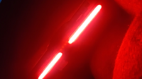
So i decided that i just wanted the RED LEDs connected, so taped the blue/green wire out the way and connected the other 4x strings to the PWM feed . . . .
this is what we had now . . . .

.

.

.

.
Perfect . . . . . .
they dimmed down perfectly . . . . . . .
But there was a sugestion about using a Resistor or small DC-DC boost/Buck converter to reduce the brightness if needed?
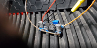
I had a DC-DC volatge droper/booster so gave it a quick go . . . . i wired it up inline with the LED string . . .

.
which seemed to give us this . . . .

.
with massive rounded off sloaps . . . .
So it looked like a DC-DC voltage droper did work but the input/output capacitors rounded off the PWM signal . . .
Im yet to try the test again with some resistors . . . . .
in the meantime its all working well and im very happy with the result... =]
This Thread continues where this one left off . . . . .
Cab Ambient Lighting (factory Mod) - How I Done It -
.....
On the previous thread we looked fitting the OEM roof light fitting, to replace it with an OEM unit with added RED LED downlights . . . . which worked out great.
Now lets look at the rest. . . . . . . . .
originally i was looking at these:
T5 T5.1 Footwell LED Lights Upgrade Kit & Trim Removal Kit
.
.
FYI there is a small 3way switch on the rear of each of the TL lights that selects the colour red/blue/white
I also got a set of OEM white LED lights from the Forum Shop via @Pauly which done the same thing . . .
The Vans lower dash panels already had the lower light cut-outs which just needed a gentle persuasion with a Stanley blade to reveal the holes . . .
Following this guide we had the lights in . . . . picking up the Curtisey light circuit (Red/bvrown & red/black)


there was a cutout guide if needed - but it wasnt =]

.
The Curtsey light feed gave us lighting in the footwell when the door was opened at night . . . we chose the White Led units . . .

.

.

Next on the agenda was the matching Red LED ambient back-ground lighting . . . . We had seen from the previous thread that you can connect LED to the Ambient light feed (at the rear of the Light control switch) that would work the same as the rest of the dash and be dimmable . . . . as the rest of the dash.....
Now orginally i was going to cut-out a second hole in the lower dash plastics to fit a second lot of LEDs (this time Red) so that the existing would come on with the open door curtsy light in white, but then at night we could have the other LEDs red one come on . . . .
just before fitting these i come across this post on Amazon . . . .
.
They looked to do the job . . . and i wouldny need to cut the dash plastics . . . . perfect i thought. =]
They were RGB and had a remote and fancey sound/music mode - sweet.
So i ordered a few sets . . . . . .
There were two versions, 12v and USB so i grabbed one of each . . .
when they arrived a quick test showed they worked great . . .

.

one thing i did notice was that the 12v versions were brighter, but both looked the same appart from the lead . . .
one had a USB end . . . one didnt . . . . but both leads worked on both units, so effectively the units were the same, but being fed from either 12v dc or 5v dc from the USB . . . that explained why the 12v setup was brighter . . . .
Over to the van we went and connected to the same 12v ambient feed as the OEM roof light . . . . . . . . . . . . . switched on for a test . . . . . and nothing. !!!
just a dim glow, remote didnt work, lights didnt work . . . . Nothing.
Tried the second set - same result =[
Getting the meter out and checking for voltage we could see that the voltage went from 11v to 2v when the dimmer roller was moved . . . . . so all good right?
well no . . . .

moving back inside everything worked as it should . . . . So what gives???????
Then it dawned on me . . . . . . Maybe VW are being cleaver and using not just a variable voltage? . . . but a variable LED driver circuit . . . . ?
Back out the van with a different meter . . . .

BINGO !!!! sussed it . . . . The amient feed is using PWM LED driver to do the dimming . . . . using a duty cycle . . .
Thats why the DVOM meter was showing a volt range of 2v to 12v . . . . it was just the RMS of the PWM signal . . . .
Also that why the new LED lights werent working . . . . they had there own LED PWM driver circuit on board that didnt like the PWM voltage being supplied . . .
a quick test later we had this . . .

i stripped out the 4x Led strings and cut out the fancy LED controller and remote etc . . . . we were left with 4wires per string. . . .
one for RED
one for BLUE
one for GREEN
and one for common -0v
once they were connected to the Ambient feed all was well =]
So the Ambient feed is a PWM LED driver as seen here at 95% on . . . . . which can directly feed the LED strings . . .


this was double checked here . . . . . .

.
So i decided that i just wanted the RED LEDs connected, so taped the blue/green wire out the way and connected the other 4x strings to the PWM feed . . . .
this is what we had now . . . .

.

.

.

.
Perfect . . . . . .
they dimmed down perfectly . . . . . . .
But there was a sugestion about using a Resistor or small DC-DC boost/Buck converter to reduce the brightness if needed?
I had a DC-DC volatge droper/booster so gave it a quick go . . . . i wired it up inline with the LED string . . .

.
which seemed to give us this . . . .

.
with massive rounded off sloaps . . . .
So it looked like a DC-DC voltage droper did work but the input/output capacitors rounded off the PWM signal . . .
Im yet to try the test again with some resistors . . . . .
in the meantime its all working well and im very happy with the result... =]


