Courtesy Light Switch Options

Resurrecting this thread.

If I wanted to install 6 round LED lights in my ceiling and have all 6 come on as courtesy lights and be able to have a dimmer switch that would control al 6 LED lights would that be possible? If so which would be the best way?

Secondly how do the touch sensitive lights work. If they were all on and then switched off by a dimmer switch, when switched on by the dimmer switch would they all come on or would each light need to be touched again to switch them on?

@Deaky @Grim Reaper
 
If the dimmer circuit was in the common feed to all 6 lights then all 6 would be at the mercy of whatever level the dimmer was set to (ie all would be dim no matter which lights were on) but I’m not sure if the touch on/off would work properly if the feed was less than full voltage. (I’m assuming a capacitive touch switch type light not a press to switch a physical on/off switch on or off)
 
It’s easily done if you use a dimmer switch or module that dims the negative side. It won’t work with touch lights because they don’t remember their last state so will always be off until they’re touched.
 
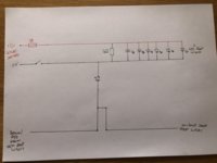
OK this is where my install is currently at. Im not sure the circuit is correct.

1. Is the 1kOhm resistor in the correct place?
2. Instead of the switch in the 0v from leisure battery I wanted a dimmer switch. I bought one from eBay but it has + and - INPUT and + and - OUTPUT. Im not sure if that will work in this circuit?

All suggestions welcomed.


image-jpg.53736
 
Can't see your picture, but is the dimmer a PWM type?

No idea (I doubt it at £5), but I wired +ve input to leisure battery, -ve input to leisure battery and -ve output to the -ve of LEDs as in the diagram and it works. Switches on / off and dims.

Only problem is either these electrics or the wiring to me heater is draining the leisure battery.
 
Both will probably take power when you think they are not in use, I’ve put a relay and switch in for my heater so it’s only on when I need it, put a multimeter in line on the amps setting to see how much is being drained.
Take the main fuse out of your leisure battery output feed and connect the meter up to the two terminals, change leads to Ammeter inputs and start out on highest scale you can and work down.
If you’re not sure how to do it, check out some you tube videos first and make sure you return the leads to the volt meter inputs when done so as not to burn your meter out next time you use it


Thanks, good idea. I will measure the current draw in each of the circuits using the remove fuse and put in the ammeter. Will report back. Im guessing its not just the heater, but also the draw from the LEDs. When I wire the 1k resistor to stop this glow will it stop the current draw? Im a bit unsure how the BCM works.
 
I can't see the image to see where you have the resistor in circuit.
Why do you have a resistor in cct?
 
I can't see the image to see where you have the resistor in circuit.
Why do you have a resistor in cct?
The resistor is in parallel to the LEDs. I only fitted it yesterday. It’s to stop the LEDs glowing very dimly.

Any idea why you can’t see the image? I will try again.
43FD160D-E943-4BCE-B24A-D9BB131018BF.jpeg
 
I see that now, so if the led’s are glowing when no doors are open or the switch on the left is not closed you must have an earth contact somewhere, draining a little current, adding the resistor will stop the leds glowing but it won’t stop the drain, the van light circuit depowers after a while, do the leds stop glowing after this time period?
To find the drain you need to break the circuit before the diode (with the resistor out of circuit) and see if the led’s go out. If they do, its the van circuit that is causing the drain .
Do the leds light no matter which way round they are connected or are they polarity sensitive. Use meter on diode setting to prove, should only get continuity connected one way round if they are.
You may be suffering what I suspected in earlier posts, your leisure battery may be trying to charge your van battery via the interior light circuit.

Thanks. I will do some investigating later. It might need to wait until weekend as its dark now when I get home from work. :thumbsup:

(Strange you cant see the other pic. Its the same one uploaded from my phone. I just rotated it 90*)
 
Have you still got any filament bulbs in the interior light circuit (original festoon lamps or capless bulbs) if you take these out does the led array stop glowing?
 
I see that now, so if the led’s are glowing when no doors are open or the switch on the left is not closed you must have an earth contact somewhere, draining a little current, adding the resistor will stop the leds glowing but it won’t stop the drain, the van light circuit depowers after a while, do the leds stop glowing after this time period?

Ok I hope to get to do a bit more research into this this weekend. How long is it before the LEDs should timeout and stop glowing?

To find the drain you need to break the circuit before the diode (with the resistor out of circuit) and see if the led’s go out. If they do, its the van circuit that is causing the drain .

SO basically this means remove the resisitor, and break the circuit where the resistor connects to the -ve lead or break the circuit by disconnecting the diode on anode side?

Do the leds light no matter which way round they are connected or are they polarity sensitive. Use meter on diode setting to prove, should only get continuity connected one way round if they are.

The LEDs are these from @travelvolts , can you answer this please? Im not sure if I can test them. If I can it will mean removing the roof.
 
The circuit you have @Skyliner33 will not time out. The +ve side is supplied by your leisure battery and not the van curtesy circuit which times out.

The BCM dimming circuit has a small constant output current that is a consequence of the unit's internal transient voltage protection circuitry. Ordinarily, the leakage current will not cause visible lighting of any LEDs connected to the dimmer, but some sensitive LEDs may be affected. The amount of current is so small it will be a negligible drain on the battery.
 
I assume you have a fuse for the lighting circuit? This is where I would put an ammeter like on your heater testing, though you'll probably only see milliamps when off.
 
Thanks guys. At the moment I have just taken the battery off and its charging as per instructions of the place I am taking it tomorrow to do a drop test (?). Disappointingly I have not got a reply yet from the place I bought it from.

More investigations and a rewire coming up when I get back from the battery tester.
 
i've taken a different approach to adding extra interior LED lights which come on with the courtesy lights. I also wanted to be able to switch the extra lights on in the back of the van while sitting in the driver's seat. And I also wanted a touch switch in the back for the passengers to operate the extra lights. And finally I wanted a clean 'courtesy lights on' signal to send to my TK103B tracker device so that it would send a text message to my phone if the van doors were opened.

The main issue was getting a suitable signal derived from the existing courtesy lights as both the -ve and +ve sides of the courtesy lights go to the BCM and do not provide a suitable voltage with respect to earth at the right times, and furthermore the voltage applied to the courtesy lights is pulse width modulated when switching on and off to create the dimming effect. All in all not a recipe for a clean signal to operate a relay and provide a suitable signal for the tracker unit!
However with a bunch of cheap modules all this can be sorted, which I have documented in the attached file, in the hope that all or parts of it might be useful to others. A remote key fob allows me to operate the lights from the driver's seat without adding extra wiring or dash switches in the van. An illluminated touch switch in the back makes it easy for rear passengers to switch the extra lights on, and all the extra lights turn on and off in tandem with the courtesy lights. Plus a clean +12v signal is available for the Tracker unit. Connection to the courtesy lights is just by connecting across any of the bulbs.
I've included a few pics in the attachment too.
PS: it's all working in my van now!
 

Attachments

  • Bob's Lighting Circuit.pdf
    330 KB · Views: 98
Back
Top