Deaky’s Kombi to Camper journey

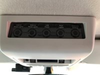
Ha ha, not a lot to report at the moment. I have a few bits in the pipe line. I'm adding a bank of isolator switches to the over head cubby hole. The RF lighting system I have installed places a 24/7 drain on the battery and throughout the winter it's meant I've had to top up the leisure battery a couple of times. I'm going to link the switches to a new relay/fuse box under the passenger seat so that when I'm not camping I can turn off the lighting system and the USB ports etc to conserve the battery. I might even drop in a lithium battery at the same time :whistle:

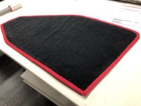
Only other thing I've done is to tart up my window blinds with a bit of red trim :D
IMG_6765.jpg
 
Ha ha, not a lot to report at the moment. I have a few bits in the pipe line. I'm adding a bank of isolator switches to the over head cubby hole. The RF lighting system I have installed places a 24/7 drain on the battery and throughout the winter it's meant I've had to top up the leisure battery a couple of times. I'm going to link the switches to a new relay/fuse box under the passenger seat so that when I'm not camping I can turn off the lighting system and the USB ports etc to conserve the battery. I might even drop in a lithium battery at the same time :whistle:

Only other thing I've done is to tart up my window blinds with a bit of red trim :D

View attachment 37913
I think you need a pillar blinds.....
 
Fantastic build Desky, a lot braver than me.

Just a quick question, do any of your interia lights, apart from the extra rear foot lights, come on with the cockpit courtesy lights at the middle of your van
 
Fantastic build Desky, a lot braver than me.

Just a quick question, do any of your interia lights, apart from the extra rear foot lights, come on with the cockpit courtesy lights at the middle of your van
I have 8 led units in the back of mine. 2 come on with the courtesy lights, 4 are on 1 zone, 2 are on another zone.
 
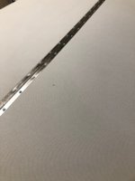
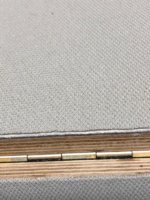
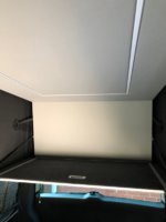
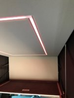
And so the final faze begins. Say goodbye to the naff hinge and the unfinished board. Say hello to some new recessed lighting connected to the mood lights and courtesy circuit. Plus some tactile light switches for just white

IMG_7159.jpg

IMG_7160.jpg
 
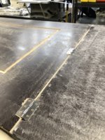
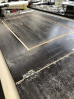
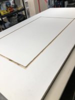
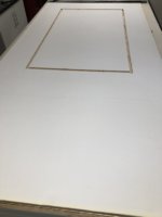
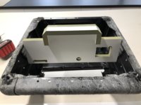
I’ve stripped the old board back and removed the piano hinge. I thought about reusing the piano hinge and maybe recessing it into the board, only problem is it’s paper thin and I don’t think I could counter sink a screw head into it and obviously I wouldn’t want to see the screw heads through the head lining material. In the end I found some normal butt hinges in B&Q that opened about 280 degrees, perfect to use them backwards so the barrel of the hinge isn’t seen and heavy gauge enough to countersink the screw heads from the back.

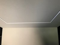
Next I cut a slot out of the bottom of the board for the led strips. I had 2 x 2meter lengths of channel left but no end caps. Hence the square layout :rofl:

08349870-F64C-494E-A132-0B9085BAF7FC.jpeg

B61719F3-8775-4D10-BFD2-15CDA13DF8A8.jpeg

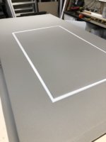
I decided to lay a 3mm closed cell foam sheet over the board before the headlining material goes on. This will help to cover the hinges.

16122D50-D5C9-48C4-8B32-F81FF070CCDC.jpeg 10D2D5DE-693F-4E4C-A340-0906ACD563A1.jpeg

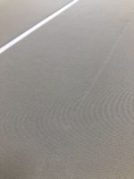
Head lining on and the light channels fitted. The mitres all lined up perfectly. The only evidence that the board is hinged is a crease across the width where it folds.

779CA9A0-92E1-4045-9805-BAD6E8DCEBBC.jpeg

5426F3EE-5835-49B1-B253-D7B30827E4B8.jpeg

Just need to finish off the sides and drop the LED’s in and it’s ready to go back in the van. :D
 
Last edited:
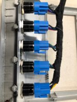
It became apparent last year that the mood lighting dimmers and other electrical items, although they only put a small draw on the leisure battery, it was running really low during the winter when the solar couldn't keep it topped up. I decided to put some switches into the circuits to isolate them when not in use. I wanted the switches to be easily accessible so I decided to make use of the cubby hole in the cab lining. Rather than extend the circuits up to the cab I decided to use relays under the seat and run a single multicore cable up to the roof.

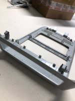
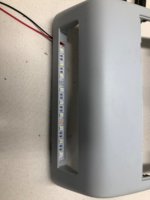
Started to install a switch panel today. I took the panel from the roof and found that the cubby hole bit is clipped to the frame.
IMG_7191.jpg

I've put some led's into it that will connect to the instrument lighting circuit.

IMG_7193.jpg

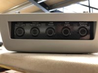
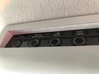
I've gone for 5 switches

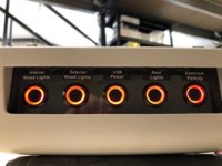
Interior mood lighting, Exterior mood lighting, USB power, Roof lights (the ones in the top of the HiLo) and also a switch to disable the parking mode on the dash cam when I'm camping.

IMG_7196.jpg

I cut up an old number plate and drilled it for the switches then covered it in some carbon fibre vinyl. I used the clips that were already in the frame and plastiwelded the panel in place.

IMG_7197.jpg

Wired it up and tested the tell tale lights

IMG_7198.jpg

Then re fitted the frame into the cab roof.

IMG_7199.jpg
 
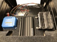
Today I’ve turned my attention the the leisure electrics under the passenger seat. I’m fitting a bank of relays that will be switched by the overhead switch panel in the roof and adding a couple more circuits. This has meant a re design under the seat.

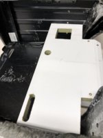
I’ve made a new hinged shelf that will hold the fuses and chargers in front of the battery.

F87DF5F3-5BF6-48E2-B0F4-7B785396204A.jpeg

It’s hinged is I can lift it up and make any connections underneath and when it’s down it will hide the existing wiring that comes into the van through the floor.

952A7CA3-169E-43F3-9C1A-08355EF2DBF2.jpeg

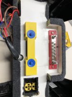
Rather than the mass of wires that were bolted to the leisure battery before I’ve installed a positive and negative busbar under the shelf so there will only be a +ve and -ve connection to the battery and the rest of the connections will be hidden away under the shelf.

B181A510-77E2-4A85-9777-ED83B551334F.jpeg

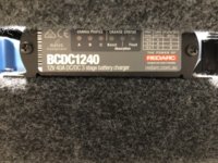
Everything fits snugly and I can see the status lights on my redarc from the front of the seat base.

E93C1C86-366D-4F38-982C-A5ADEEF97FC4.jpeg

C35F1B1C-66F9-4FD7-949A-6C10EBAD068E.jpeg
 
Nice work, but why do you need to blue MTTP box, doesnt the REDARC have that inbuilt?

Is the yellow and blue think the positive busbar?
TIA
 
Nice work, but why do you need to blue MTTP box, doesnt the REDARC have that inbuilt?

Is the yellow and blue think the positive busbar?
TIA
The open circuit voltage of my 250w panel is too high for the Redarc. The yellow and blue thing is the negative busbar with its cover on.
 
Back
Top