Fitting a battery charger with a Sargent EC155

After cooking a leisure battery last year (the carbon monoxide alarm went off…hydrogen gas?? using EC155. I now have a better understanding as to how the PSU works, and how it’s not ideal for long periods of hook up to 240v with the charger left on. I’ve ordered a Victron 12/10 smart charger to remove the need for the Sargent PSU / charger circuit to be used.

Given I have 240v and leisure battery 12v cable runs neatly to the back corner where the EC155 is mounted - any reason I can’t tap into the 12v supply as a circuit for Victron charger output?
 
I’m not sure you can separate the charger function in the unit. You could maybe remove all mains from the Sargent and direct to the separate charger instead but then you need a consumer unit etc too and the Sargent becomes glorified a 12v fuse box.

I have the Sargent unit and I’d like to upgrade my battery when it fails but having investigated briefly when Lee had a battery for sale I decided it was not easily doable and so would wait until required. I’d be interested to hear if you find a viable solution in the meantime without losing the functionality of the unit.

Have you tried contacting Sargent?

I'm finally in the process of butchering the Sargent ec160 panel in my Redline camper conversion my thinking is to remove the 20A fuse (and block that) to the inbuilt charger circuit then loop out from one of the two spare 230V mcbs on the Sargent to take a feed to a Victron smart charger next to the seat base leisure battery.
I've got most of the major items here including solar panels but no wiring as yet and laying out the installation logically when the Roamer takes up pretty well all the seat base and trying to retain the Sargent ec160 which is where the conversion company have taken all their 12V ccts (apart from the Webasto) is doing my head in!
 
So having read many many threads I now have a plan…

I welcome any comments before getting the wire cutters out tomorrow! Particularly from @Dellmassive

Plan is to:
  1. disable the Sargent charger/Psu circuit (pulling the 12v fuse and turning off 240v breaker
  2. tap into the supply feeds from each battery as they emerge from the carpet below the Sargent - Wago connectors probably best?
  3. Wire the charger and each battery to this On-Off-On double poll double throw switch to toggle between charging Van and Leisure batteries (winter mode vs summer mode)
  4. On the 240v EHU side, add a fused spur out of sight to supply the Victron smart charger.
Hopefully minimising additional/visible cable runs as the van is fully converted.

I’ve circled everything to be added in pink below:

7579DF8C-08E4-426A-A750-D338BCC67E53.jpeg
 
Last edited:
@andyhasalandy Do you have a VSR under the drivers seat on your conversion ie. is it a Redline van as they love ignoring the reality of the smart alternator on a T6.
The reason I mentioned the VSR is that on my conversion I have the VSR in the seat base and the EC 160 in the wardrobe where you have the other end of the two battery input wires from the seat base at the panel as well as the engine running trigger wire.
At the moment I'm not going to bother with a charger for the starter battery and have (hopefully) disabled the Sargent charger but have got a separate Victron 12/30 smart charger behind the seat base for the leisure battery and a Renogy DC 50 B2B/mppt charger in the seat base again for the leisure battery.
Having fairly easily dismantled much of the kitchen in my van there's plenty of room behind there to provide a route for additional cables and priest hole plus behind the drivers seat there's room at low level which is where I've got my Victron smart charger now and possibly in the future an inverter for an alternative 13A skt by the mains hook up one at the wardrobe.
 
All the grounds are connected together anyway, so no need to switch the negative side of the output of the victron, just the positive side. I used two small battery cut off switches to do something similar with my solar panel output and by pulling the key out of one cut off switch and moving it to another I can either send the solar output to the starter battery via a charge controller or to the leisure battery via the DC\DC charger but never both (so long as I don't insert two keys into both cut off switches at the same time)
Oh and I personally wouldn't use Wago connectors in the van for DC, they are good and I keep some for emergency use but van charger wiring could be up to 25mm2 depending on the run length and wagos won't take that size conductor.
 
Last edited:
Is the victron fed from an inverter output from the EC155 or is it a pass through from the EHU? If it's an inverter output is the inverter output a pure sine wave and if not will the victron like it if it isn't?
 
Is the victron fed from an inverter output from the EC155 or is it a pass through from the EHU? If it's an inverter output is the inverter output a pure sine wave and if not will the victron like it if it isn't?
Straight pass through, no inverters involved. Thank you for the advice on wagos.
 
@andyhasalandy Do you have a VSR under the drivers seat on your conversion ie. is it a Redline van as they love ignoring the reality of the smart alternator on a T6.
The reason I mentioned the VSR is that on my conversion I have the VSR in the seat base and the EC 160 in the wardrobe where you have the other end of the two battery input wires from the seat base at the panel as well as the engine running trigger wire.
At the moment I'm not going to bother with a charger for the starter battery and have (hopefully) disabled the Sargent charger but have got a separate Victron 12/30 smart charger behind the seat base for the leisure battery and a Renogy DC 50 B2B/mppt charger in the seat base again for the leisure battery.
Having fairly easily dismantled much of the kitchen in my van there's plenty of room behind there to provide a route for additional cables and priest hole plus behind the drivers seat there's room at low level which is where I've got my Victron smart charger now and possibly in the future an inverter for an alternative 13A skt by the mains hook up one at the wardrobe.
Interesting thank you. Don’t have solar to consider but do have a Sterling DC-DC under the drivers seat to keep the leisure topped up from the van when driving. It’s a Acura conversion, similar to Redline by the sounds of it
 
I am currently going down a different path for my AGM LB. I have open up the Sargent and removed the 13.5v AC to DC unit. I have kept the Charger switch as an AC feed to my Victron charger, from which I feed the output back into the Sargent, connecting to the original internal13.5v spade connections. Planning to feed the Solar down the same path so that Sargent retains control of which battery I charging. Happy to post pics as I build this up.IMG_20230328_152632.jpg
 
I am currently going down a different path for my AGM LB. I have open up the Sargent and removed the 13.5v AC to DC unit. I have kept the Charger switch as an AC feed to my Victron charger, from which I feed the output back into the Sargent, connecting to the original internal13.5v spade connections. Planning to feed the Solar down the same path so that Sargent retains control of which battery I charging. Happy to post pics as I build this up.View attachment 193939
Neat. Keen to see how you get on with this
 
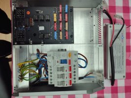
So I have completed the dry run assembly with the following steps:
1 Removed 4 anti tamper torx screws to open Sargent EC155( replaced with hex bolts)
2. Removed 13.8v internal charger (disconnect AC from Charger switch and pull DC blade connectors on PCB.snip wiring
3 Drilled and grommet hole on RHS for AC supply to Victron Charger from switch. Likewise on LHS for Victron DC output return to male spade connectors
4.made up female spade connectors for AC switch reusing plastic protectors. Likewise for DC side With heat shrink protection. Connected VictronConnect charger earth to earth bus too,
5. Reassemble in Van and see what happens. Hopefully all Sargent control of which battery to charge will be retained without need to tap into wlring loom. Have left a generous run of cable between Sargent and VictronConnect so I can remove either easily at later date for Solar connection.

A5929398-6FAC-4D77-B033-60D222DCA9D9.jpeg

E8EFAEE5-C4F8-4795-865E-11A6B4CB4D39.jpeg

8A052007-E52F-4F06-9586-3616355CC5D2.jpeg

E63F07CD-AD29-429B-BCC2-FDD608E2DECF.jpeg
 
Last edited:
  • Like
Reactions: CAB
Are the MPPT and smart charger located in the wardrobe along with the Sargent unit, just thinking it would be a bit of a distance to the leisure and starter batteries with fairly high currents ie. chunky cables?
 
I am relying on the rating of the original Sargent cable loom with the whole system pinned at 20amps. Personally if I were doing the conversion (this is a Revolution Ricos T6), I would have gone for extra girth than afforded by the existing brown/blue and brown/green cabling. There is probably no more than 3-5metres of run. The charger is 15amps but I will monitor and the internal constant voltage charger was 16amps.
 
Our van is a Redline conversion and the 12v supplies to the leisure and starter battery was a 2 core multi strand flex that looked to be about 2.5mm2 per conductor. This connected to either side of the SVR they installed to loop onto either the starter feed in or the other side of the relay and the leisure battery.
My thinking was that these conductors weren't a big enough CSA for the job so they're now connected in parallel and connected to the leisure battery only.
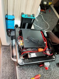
I've installed a Victron 30A 30/12 charger for the leisure battery behind the drivers seat and fed this from one of the spare 230Vac MCBs in the Sargent unit, I haven't got a separate starter battery charger and have disabled the charger in the Sargent by removing the charger fuse and having taken the conductor out of the SB connection on the Sargent.
Having fitted a fairly hefty lifePO4 seatbase battery and blown two fuses (an 80A and 50A) so far I'm becoming rapidly aware of the big currents drawn at fairly modest wattages when you're running at a nominal 12Vdc, ie. 50A from a B2B charger, 88A running what turned out to be an 1100 watt 230Vac fan heater from an inverter, proper chunky current draws compared to the same 1100 watts at 230Vac being around 5A.
IMG20230323135956.jpg
 
Our van is a Redline conversion and the 12v supplies to the leisure and starter battery was a 2 core multi strand flex that looked to be about 2.5mm2 per conductor. This connected to either side of the SVR they installed to loop onto either the starter feed in or the other side of the relay and the leisure battery.
My thinking was that these conductors weren't a big enough CSA for the job so they're now connected in parallel and connected to the leisure battery only.
I've installed a Victron 30A 30/12 charger for the leisure battery behind the drivers seat and fed this from one of the spare 230Vac MCBs in the Sargent unit, I haven't got a separate starter battery charger and have disabled the charger in the Sargent by removing the charger fuse and having taken the conductor out of the SB connection on the Sargent.
Having fitted a fairly hefty lifePO4 seatbase battery and blown two fuses (an 80A and 50A) so far I'm becoming rapidly aware of the big currents drawn at fairly modest wattages when you're running at a nominal 12Vdc, ie. 50A from a B2B charger, 88A running what turned out to be an 1100 watt 230Vac fan heater from an inverter, proper chunky current draws compared to the same 1100 watts at 230Vac being around 5A.
View attachment 194046
I am not an electrician like you but when exploring an installation of DC equipment soon began to realise just how much current draw there is and the importance of both fuse and cable rating.

I do like your idea of mounting the charger behind the driver's seat. It is otherwise dead space. The MPPT can go there too.

I will try a fit of what I have done but will see what the Victron shunt says about current draw before permanently mounting it. I have a separate 25amp charger that can service the VB albeit via the EHU sockets and an extension out the window and under the bonnet (was looking at fitting SAE connectors under the dash)

Dave
 
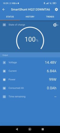
Dry run fit complete and it works to a point. The leisure battery is being charged and will continue to charge while on EHU (mppt not yet connected). Control panel for the EC155 does it's normal functions in parallel. Thought however that when you switch to the VB on the control panel that the Sargent would switch the charge to the VB. Getting a Victron alarm beep instead. Need to explore.

IMG_20230330_102917.jpg

Screenshot_2023-03-30-10-29-57-544_com.victronenergy.victronconnect.jpg
 
Without a shunt on the starter battery too though you won't know the state of charge there?
I've never used my Sargent EC160 to charge the starter battery as it hasn't been a"thing" with the starter battery being low on charge although in fairness it's not the original Moll, VW replaced that under warranty.
On my setup I'll just turn on the Victron at that single 13A skt in the picture when on hookup if needed depending on what the shunt indicates is in the battery. Solar during the summer and B2B from driving will probably mean the leisure battery will need deliberately draining rather than charging at times?
 
New to T6s and have noticed they place quiet a demand on the VB. So have a BM2 on that but might put another Shunt on it. Might just pull the EC155 fuse and keep it completely independent of the LB. With the Solar that should be enough for the LB. Inclined to but an SAE connector into the engine bay and do what you are doing with the LB ☺️
 
  • Like
Reactions: CAB
Back
Top