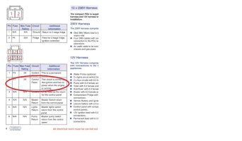
Which... isn't much help as it's rather vague. At least the comparable Sargent systems have a link so that you could choose to remove it, the BCA systems seem to be rather more killjoy in that aspect.
I think you are down to putting in an additional system to do what you want, which is a shame.
I'd suggest putting in 12v sockets so they don't need switching and then using plug in USB adaptors. If you go with fitted USB sockets first test them to see what the idle power draw is, you could either fit switches next to them, or maybe you could fit a master switch in your electrics area so that you can isolate them when leaving the van off hookup for any length of time?
You might want to think about using one of the small fuse boxes with both negative and positive bus bars - that would give you some future expansion options.
For instance this one: Fuse Box With Common Power & Ground Busbars - 6 Way
This has a split positive bus bar, so what you could do is to move the leads that go from the Victron MPPT to the LB to one of the positive bus bar inputs and the negative bus bar. You can then put a fresh set of leads in from those bus bars (through a suitable fuse) to the Victron. That makes your first positive bus bar the "permanent" feed from the LB. Then get a suitable switch to link the first positive bus bar to the second - this makes the second bus bar the one for things like USB that have a small idle load that you would want to disable when parked up off grid.
And then you have a couple of spare ways for future things like if you wanted to add a 4G modem or something.

