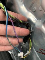
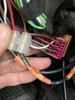
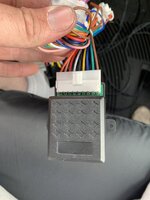
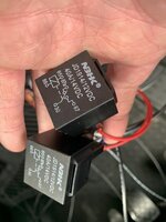
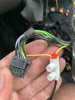
Retrofit: Power fold mirror with fold on remote lock

Some information for those taking the genuine route:

Wire crimps mirror end (4x) - 000979132E
Wire crimps switch/window motor (6x) - 000979009E

Just to help get the mirror wiring the right way round first time, for both mirrors:

Pin 14 (window motor) -> Pin 11 red/black (mirror)
Pin 15 (window motor) -> Pin 12 brown/red (mirror)
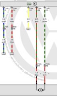
407445F7-D13B-4B4F-AAA0-3B19678E0DC2.jpeg E1648F17-5B7C-44C5-B9A8-6C60EE1BE53C.jpeg
 
Last edited:
hi Robert, thanks for the information, can all this wiring be done from the drivers side door card? Are both outputs for the two wing mirror motors in the drivers door card? Any idea which worries these are? Going to have ago tomorrow.
Thanks Ash
This wiring diagram applies to aftermarket approach and unfortunately you have to run two wires from LHS folding motor to wherever you are going to locate your folding control module( e.g. driver's door, BCM area)
 
  • Like
Reactions: mmi
This wiring diagram applies to aftermarket approach and unfortunately you have to run two wires from LHS folding motor to wherever you are going to locate your folding control module( e.g. driver's door, BCM area)

Thanks for the replay rob, which is the best way to run the wires? My t5 kombi has the folding mirrors so I’ve purchased the items to wire it up on lock. Are there any videos out there of people installing this kit?
Cheers Ash
 
Thanks for the replay rob, which is the best way to run the wires? My t5 kombi has the folding mirrors so I’ve purchased the items to wire it up on lock. Are there any videos out there of people installing this kit?
Cheers Ash
I haven't seen any installation videos but this mod is extremely simple.
You just need to run 2 wires from your LHS folding motor to the BCM area.
Then run another 2 wires from RHS folding motor plus locking signal(I have finally ignored unlocking signal).
Next is permanent and ignition switched power (you will find these at central fuse board). After connect everything together as per the diagram and job is done ;) :thumbsup:.
 
  • Like
Reactions: mmi
I haven't seen any installation videos but this mod is extremely simple.
You just need to run 2 wires from your LHS folding motor to the BCM area.
Then run another 2 wires from RHS folding motor plus locking signal(I have finally ignored unlocking signal).
Next is permanent and ignition switched power (you will find these at central fuse board). After connect everything together as per the diagram and job is done ;) :thumbsup:.

Thanks I will have a go :) where about did you mount the relays etc? Did you run everything back to a central location? Next job is find out where the bcm is! Did you have a wiring diagram to find which cores were ignition power, motor etc or just traced them back?
Cheers Ash.
 
cheers, did you bring all the wires back to one place? Where did you mount your relay?
I ran all wires to the BCM area, right it front of it. All of my terminations are there and folding module plus 2 relays ;). It is handy location just in case, but so far (it is in operation for nearly 20 months) no problems whatsoever :thumbsup:.
 
Did you use piggy back fuses from the main fuse board for the live and ignition live or connect it from elsewhere? Cheers Ash
I actually had spare slots on my main fuse board so I attempted to keep it OEM like.
 
  • Like
Reactions: mmi
Thanks! Some slight issues with mine .

my colours from the after market relay aren’t in the Same order as yours but the function descriptions are the same.


I've wired the lock and unlock signal from the driver door purple and blue yellow. These literally go high for less the second my multimeter won’t register the voltage quick enough.

DD6C1ECF-164A-48E7-B42D-BF020405FA70.jpeg

From the above diagram I picked up the motor connections red brown, red black from both doors?
5CA38412-817E-4105-8881-DD52AB85B0A3.jpeg
This is my aftermarket relay and 12v relays.
84BB2424-B280-4A5B-B99E-20E693D16D0C.jpegBDD45523-9C56-4BBA-892A-F096D258FC58.jpeg
I already had a motorised switch installed so picked up the core from pin 8 yellow.7809D6A5-5308-4E6E-AB79-BFA1B3FE857B.jpeg
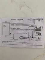
This is my wiring diagram that came with the aftermarket relay.
6C1BF75B-7B3F-43B5-99E5-CD91ED3F1C1C.jpeg Any help would be great lol.
 
There is a jumper switch on the wiring diagram but can’t seem to find it on the relay unless it’s inside? Don’t think I need it anyway.
 
It depends what's your preferred way of unfolding your mirrors. I have eventually chosen unfold on ignition ON. And this was achieved by disconnecting the unlocking signal.
 
  • Like
Reactions: mmi
They open when opening the van but close when I take the key out of the ignition? Is that right? I thought they’d close when locking?
 
This is unusual to me but maybe your module has some additional functionality?

Generally speaking your mirrors should unfold when you unlock the van (your unlocking signal is connected). And then they should fold in when you lock the van.

Is your mirror manual folding switch functioning correctly?
Are you sure that you haven't mixed unlocking signal with locking?
 
  • Like
Reactions: mmi
Back
Top