You are using an out of date browser. It may not display this or other websites correctly.
You should upgrade or use an alternative browser.
You should upgrade or use an alternative browser.
T6 Vs T6.1 Lights
- Thread starter Pauly
- Start date
So it goes on the light connector not the van connector
I doesn’t matter. As long as it’s connected between to two wires going to the indicators.So it goes on the light connector not the van connector
Steve light
New Member
Thanks for your help on this write up guys. Fitted and coded out all working..
@LambethBoy i shamelessly copied your diagram from an earlier post , and like being at school again, I’ve been caught out!
So would you be able to answer the above from your experience?
If not I believe the wiring diagrams are available to view with VIP membership @4ndy
 , and like being at school again, I’ve been caught out!
So would you be able to answer the above from your experience?
If not I believe the wiring diagrams are available to view with VIP membership @4ndy
So, if my eyes aren't deceiving me, its orange and green I bridge?Here is mine.
View attachment 74251
All,So, if my eyes aren't deceiving me, its orange and green I bridge?
FYI - It is the Orange and Green wires that need bridging with the resistor on both units.
All sorted
Just remember the brown ground wire changes colour after the connector - once I realised this fitting was easy but if your instructions, like mine, give a PIN number for the indicator wire but just states “brown wire” for ground it can leave you scratching your head for a bit with indicating brake lights 

I went with a different location as I use my hazards frequently, to dissipate the heat, I wanted my resistors bolted to a metal frame.
I went under the front passenger seat, screwed the resistor to the frame and tapped into the rear indicator feed there. I was testing the circuit so fitted the horrible scotch locks. I will use a proper wiring pin and bring both wires together in the plug housing for future installations. The other resistor lead is earthed. No rapid flash.
Also with the non LED type lights originally fitted to my van, I ran a second reverse and a second fog to get two fogs and two reverse on the new T6.1 lights instead of only one reverse and one fog without the mod.
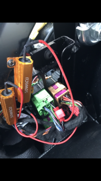
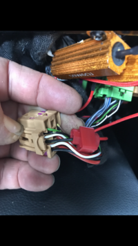
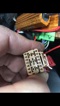


Last edited:
andyrap
T5.1 to T6.1 facelift
I went with a different location as I use my hazards frequently, to dissipate the heat, I wanted my resistors bolted to a metal frame.
I went under the front passenger seat, screwed the resistor to the frame and tapped into the rear indicator feed there. I was testing the circuit so fitted the horrible scotch locks. I will use a proper wiring pin and bring both wires together in the plug housing for future installations. The other resistor lead is earthed. No rapid flash.
Also with the non LED type lights originally fitted to my van, I ran a second reverse and a second fog to get two fogs and two reverse on the new T6.1 lights instead of only one reverse and one fog without the mod.
View attachment 116467
View attachment 116468
View attachment 116469
View attachment 116470
View attachment 116471
That's a great solution tapping in to the connectors there.
So on the green plug tap into the black/whiteI went with a different location as I use my hazards frequently, to dissipate the heat, I wanted my resistors bolted to a metal frame.
I went under the front passenger seat, screwed the resistor to the frame and tapped into the rear indicator feed there. I was testing the circuit so fitted the horrible scotch locks. I will use a proper wiring pin and bring both wires together in the plug housing for future installations. The other resistor lead is earthed. No rapid flash.
Also with the non LED type lights originally fitted to my van, I ran a second reverse and a second fog to get two fogs and two reverse on the new T6.1 lights instead of only one reverse and one fog without the mod.
View attachment 116467
View attachment 116468
View attachment 116469
View attachment 116470
View attachment 116471
On the brown plug tap into the green/black
Is that correct?
Also what route did you run your wire through to the other light to do your double reverse light/fog?
Thanks
They are the correct colours BUT one of the plugs has two wires the same colours, but the other way round ( I can’t remember just now but something like SWGN instead of GN/SW or WS/SW instead of SW/WS) if you connect it to the wrong wire you will still get rapid flash on one side. Look at a wiring diagram to make sure you get the right pins. I am not near my computer but will have a look later. NB WS is white GN is green and SW is black, don’t want to teach you to suck eggs as don’t know how familiar you are with CFD’s, or current flow diagrams.So on the green plug tap into the black/white
On the brown plug tap into the green/black
Is that correct?
Also what route did you run your wire through to the other light to do your double reverse light/fog?
Thanks
I went up the pillars to the roof and picked up the loom in the left rear upper section. See images
I used yellow repair wire (this indicates to every VW workshop an additional wire or repair has been made) and crimped the correct connector on the end rather than using a short repair wire and having to connect to that, then run an extension wire which makes a bulky loom rather than having it look original (some people just want to make it functional, but I take a bit longer so it looks right, that way if it does go into a workshop they don’t immediately think sh1t what is going on with this rats nest).
For interior looms, use the soft flocked tape to tidy up afterwards.
When adding the additional wire to the light plug, use normal good quality insulation tape like they did from the factory. Don’t poke a hole in the body grommet to get the wire through, unwind the factory tape, place the wire through and apply new tape in the same way they did to seal it correctly around the grommet. Use a wire seal on the repair wire to seal the connector.
I had to convert from standard lights to 6.1 lights in the pic so had to fit a new connector which is why all the wires are loose in one shot.


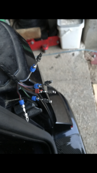

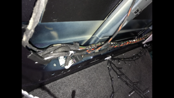
Last edited:
Thanks mate, I've just gone from T6 Halogens to T6.1 LEDS re-pinning the plugs. Now just waiting on the resistors to fit in and would like to run the wire to get the twin functions.They are the correct colours BUT one of the plugs has two wires the same colours, but the other way round ( I can’t remember just now but something like SWGN instead of GN/SW or WS/SW instead of SW/WS) if you connect it to the wrong wire you will still get rapid flash on one side. Look at a wiring diagram to make sure you get the right pins. I am not near my computer but will have a look later. NB WS is white GN is green and SW is black, don’t want to teach you to suck eggs as don’t know how familiar you are with CFD’s, or current flow diagrams.
I went up the pillars to the roof and picked up the loom in the left rear upper section. See images
I used yellow repair wire (this indicates to every VW workshop an additional wire or repair has been made) and crimped the correct connector on the end rather than using a short repair wire and having to connect to that, then run an extension wire which makes a bulky loom rather than having it look original (some people just want to make it functional, but I take a bit longer so it looks right, that way if it does go into a workshop they don’t immediately think sh1t what is going on with this rats nest).
For interior looms, use the soft flocked tape to tidy up afterwards.
When adding the additional wire to the light plug, use normal good quality insulation tape like they did from the factory. Don’t poke a hole in the body grommet to get the wire through, unwind the factory tape, place the wire through and apply new tape in the same way they did to seal it correctly around the grommet. Use a wire seal on the repair wire to seal the connector.
I had to convert from standard lights to 6.1 lights in the pic so had to fit a new connector which is why all the wires are loose in one shot.
View attachment 125659
View attachment 125660
View attachment 125661
View attachment 125662
View attachment 125663
The lights are better for just dual reverse LEDs alone 

Definitely Orange and Green then? HahaAll,
FYI - It is the Orange and Green wires that need bridging with the resistor on both units.
All sorted
Doing this tomorrow.
Similar threads
- Replies
- 11
- Views
- 428
- Replies
- 1
- Views
- 274
- Replies
- 25
- Views
- 1K
- Replies
- 0
- Views
- 231
- Replies
- 8
- Views
- 942


