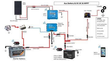
Upgrading the Factory Leisure Battery set up (+ additions)!

TallPaul_S

Senior Member
VIP Member
T6 Legend
This is my current set up in my 2018 Caravelle, a mess of wires of a Factory specced Eberspacher Auxiliary air heater and 2nd battery, plus a few extras fitted by the previous owner, all under the passenger seat:
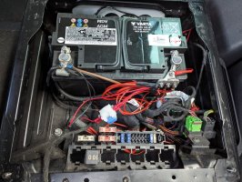
1000006404.jpg


This is the wiring diagram as it sits:
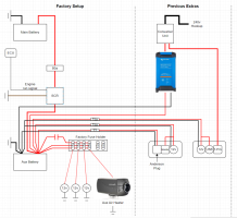
image.png

I've got the standard split charge relay, and the 75Ah AGM battery feeding 3x 12v USB ports and the air heater, from factory. It's also feeding an Anderson connector, basic battery monitor, and 12v socket on a passenger seat board:
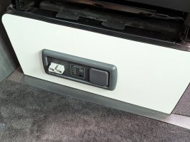
PXL_20230703_182753872.jpg

And a 12v socket and dual USB socket on the drivers seat board:
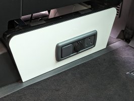
PXL_20230703_182749555.jpg


Also under the driver's seat is a 240v consumer unit with hook up lead under the bonnet, going to a Victron IP22 12/15 1 output charger and a 3 pin plug under the driver's seat.

As it is, with the limitations of the SCR, my 75Ah AGM battery only has 22.5Ah of usable capacity.

I'm currently building a kitchen pod which will have in it, a CRX50 fridge, plus some LED lights, a couple of USB ports and a submersible pump for water.

So, I want to upgrade my current set up slightly - mainly getting some proper battery monitoring via a Victron BMV-712, and as they seem to be short on stock until march I'll probably try and pick up the new Victron XS 50a B2B charger.

Also adding (moving) the Anderson connector on the passenger side to the drivers side so I can use that as a single connection for my kitchen pod.

This would mean I'd have a whole 37.5ah of battery capacity at my disposal!! And, crucially, I'd be in a much better place to be able to upgrade to a LiFePO4 battery and/or add solar in the future.

I'm aiming to be able to go away for 2-3 nights and I'd like to have a fridge and lights/water for that time. I know I'll need either solar or a bigger battery to really do this properly without having to drive, however I'll be driving a bit on a normal 2 or 3 day trip so should be ok for now.

So, proposed set up is below:
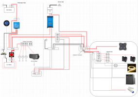
image.png


The main changes are a master 150a Megafuse and isolator switch on the LB.

Positive connections all going to a Busbar under the passenger seat.

DC-DC Victron charger in place of the SCR
Victron BMV-712

Factory fuse box etc tidied up under the passenger seat so that if (when) I upgrade to a LiFePO4 battery I'll just be able to slot a seatbase battery in! Yeah, ok... maybe not quite that easy!

Then under the driver's seat:
Fusebox for all the auxiliary non factory stuff, so the USB, 2x 12v sockets and the Anderson connector.
A negative Busbar for the above auxiliary stuff, and the battery charger.

I'm probably missing some fuses, bearing in mind the longest run of any wiring will be between the front seat bases.

And I'll need to check on what size wires I need, hopefully I'll only need 3 sizes: big beefy boy for the negative battery connection to the BMV712 shunt and to the chassis ground, and the same size for the Megafuse and isolator to bus bar. Then some 60a rated stuff for the DC-DC charger and Anderson connector, then 20a rated stuff for everything else.
 
Last edited:
Looking good.

The BMV smart shunt uses super large M10 bolts.... So make sure you get some M10 lugs.

The isolator and megga holder is normally m8 or m6.

As you say some fuses needed here and there.

Lithium battery is a game changer so look at doing that at the same time.
 
The factory install is compact though, it has that going for it. It's not the most extendable if you want to add lots.

My thoughts are either do the minimum to get your kitchen pod working or do the lot and go lithium.

I don't see the point of putting the bus bars in and isolator for the AGM and then having to shuffle them or even replace them when you go lithium and move everything around.

You should have space with the new smaller Orion to just get that in to replace the split charge relay with minimal changes and then get a fused feed across to another Anderson connector, or even just sacrifice the 15A feed you have there already as I suspect it will be much more convenient to use 12v socket or USB on the kitchen pod?
 
Looking good.

The BMV smart shunt uses super large M10 bolts.... So make sure you get some M10 lugs.

The isolator and megga holder is normally m8 or m6.

As you say some fuses needed here and there.

Lithium battery is a game changer so look at doing that at the same time.
Cheers!

Yeah I'll check the terminal sizes, I'll probably get some pre made cables for the main battery cables as I don't have a crimper big enough.

Looks like nowhere has stock of the Victron XS 50a so that might have too wait until March! And obviously I can't do lithium until I get a DC-DC charger.

General role of thumb is to fuse to protect the cable runs, right? So if there's any long runs, fuse at both ends. All my runs will be at most 2-3ft long.
 
If you have the factory electrics then your feed is already fused at one end and I assume you'll leave that in place - but replicating the 80a fuse at the seat end is a good move as in a fault it should be that one that goes not the harder to get to battery one.

I can't see that any another run is going to need fusing at either end, I'd just fuse as close to the source as possible and appropriate for the cable and load.
 
The factory install is compact though, it has that going for it. It's not the most extendable if you want to add lots.

My thoughts are either do the minimum to get your kitchen pod working or do the lot and go lithium.

I don't see the point of putting the bus bars in and isolator for the AGM and then having to shuffle them or even replace them when you go lithium and move everything around.

You should have space with the new smaller Orion to just get that in to replace the split charge relay with minimal changes and then get a fused feed across to another Anderson connector, or even just sacrifice the 15A feed you have there already as I suspect it will be much more convenient to use 12v socket or USB on the kitchen pod?
Cheers!

My idea with the isolator, bus bars etc was to put them on a plywood plate at the front of the seat base, isolator facing forward with the Megafuse and Busbar on the back. Same with the shunt for the BMV-712. So all tucked out of the way essentially under/where the current fuses & relay is.

I'd leave space for the Orion, so that when I can get one and upgrade to lithium I'd just need to swap out 2 connections too the Megafuse and the shunt.

As it looks like there's no stock on the Orion I could do as you say and just swap the Anderson connector over, that would be a 10 minute job. Then do the isolator etc when I've got the Orion.
 
If you have the factory electrics then your feed is already fused at one end and I assume you'll leave that in place - but replicating the 80a fuse at the seat end is a good move as in a fault it should be that one that goes not the harder to get to battery one.

I can't see that any another run is going to need fusing at either end, I'd just fuse as close to the source as possible and appropriate for the cable and load.
Yeah the factory set up has a 100a in the ebox under the starter battery and an 80a just before the SCR. I'd use the 80a that's already there for the Orion feed.
 
Unrelated (but connected) to the LB wiring, I've just ordered a BM2 battery monitor, Victron IP65 12/5 charger and cigarette lighter socket adapter - my main starter battery has been getting low over the last few weeks and I've literally only driven about 20 miles in about 6 weeks. With me working on building stuff in the van it means I'm constantly unlocking and opening the electric sliding doors and the starter battery is getting a beating. So this will let me monitor the starter battery, and plug in the hookup then the IP65 charger to the internal 3 pin and cigarette socket in the dash to charge both batteries when required.
 
Last edited:
View attachment 226597


The main changes are a master 150a Megafuse and isolator switch on the LB.

And I'll need to check on what size wires I need, hopefully I'll only need 3 sizes: big beefy boy for the negative battery connection to the BMV712 shunt and to the chassis ground, and the same size for the Megafuse and isolator to bus bar. Then some 60a rated stuff for the DC-DC charger and Anderson connector, then 20a rated stuff for everything else.

Hi what size cable did you go with for the negative battery connection to the chassis ground, and positive for the Megafuse and isolator to bus bar.

25mm or 35mm2

Looking to do the same cheers Jim
 
Hi what size cable did you go with for the negative battery connection to the chassis ground, and positive for the Megafuse and isolator to bus bar.

25mm or 35mm2

Looking to do the same cheers Jim
I haven't actually started on any of these changes yet, however I would be going for 35mm cable (rated for 240a) in my set up, possibly bigger (40mm, 300a) if I was planning on adding an inverter at any point.

You'd need to do the calculations based on what you've got in your system and the max possible draw on it.
yeah ok I'll need to add everything up, but I have not purchased it all yet but I suppose:


12v fridge - 60w5A
LED strip lights - 15w1.25A
2 reading lights with usb sockets - 6w1A
water pump - 4A
Hob ignition 1.8 kw - 1.8w0.15A
12v AUX socket - ?
USB c sockets x 2 - 3A
total = 14.4A

So 25mm should cover it
 
yeah ok I'll need to add everything up, but I have not purchased it all yet but I suppose:

12v fridge - 60w - 5A
LED strip lights - 15w - 1.25A
2 reading lights with usb sockets - 6w - 1A
water pump - 4A
Hob ignition 1.8 kw - 0.15A
12v AUX socket - ?
USB c sockets x 2 - 3A

total = 14.4A

So 25mm should cover it
What amp is your charger? Do you have solar?

Although I'm not actually sure if you need to include those in the total amperage as they would be charge, and the rest of the kit is discharge...

In my eyes it's better to be a bit overkill, and it's only for the main (short) runs to the busbar and chassis ground. Not forgetting you want a Megafuse of lower rating than your cable.
30 A Victron
75A solar victron charger

Could always go 35mm to be overkill

Here is my proposed diagram adopted from Dellamassive

I'm Just unsure on battary cable and megafuse size

T6F-PP-DC-DC---mppt-Jimthevan-.jpg
 
Although I'm not actually sure if you need to include those in the total amperage as they would be charge, and the rest of the kit is discharge...
It depends on the wiring arrangement - you need to consider the worst case maximum current flow over that cable and size to that.

Negative bus bars/cables are the one to watch - it's very easy to focus on all the positive circuits but overlook that all those current flows will also be going back through the van chassis and the link from that to the negative side of your source.
 
Hi @TallPaul_S - I stumbled across this old(ish) thread and wondered if you went ahead with your electrical upgrades?

I'm looking to upgrade the factory-spec leisure battery with a 100ah eco worthy lithium battery and a renogy dcc50s dcdc charger/mppt. (picked these up with a great ebay discount last week).

Maybe a stupid question, but I wanted to check - can the existing wiring for the factory fitted auxiliary battery be used to connect up the dcdc charger and save running new cables from the starter battery? Is there anything I need to consider/watch out for here?

Also, I understand that my t6 (2018/eu6) has a smart alternator, so will need a signal cable from the alternator to dcdc charger. Again, maybe a daft question, but is there an existing cable in the factory setup that can be used?
 
I haven't got around to upgrading the charger yet, but if you have the factory auxiliary battery then you've got all the wiring you need already in place.

There's a 100a fuse in the e-box under the battery which then goes to the passenger seat base, then to a 100a relay, which has 4 connections: 1 from starter battery, 1 ground, 1 engine signal wire and 1 going to an 80a fuse when then goes to the positive of the auxiliary battery.

So, to fit a DC-DC all you need to do is snip off the 100a relay (and therefore the 80a fuse) then add a fuse before connecting to your DC-DC charger. If you need it, you can use the engine signal wire from the relay.
 
There's a 100a fuse in the e-box under the battery which then goes to the passenger seat base, then to a 100a relay, which has 4 connections: 1 from starter battery, 1 ground, 1 engine signal wire and 1 going to an 80a fuse when then goes to the positive of the auxiliary battery.

I'm just getting around to starting the install (just the lifepo4 battery, Renogy DCC50S and Renogy 1000W inverter at the moment) and have found the 100A relay and 80A fuse next to the leisure battery. The wiring does indeed look as you have detailed above (couple of pics below). Am I on the right tracks here?

I plan to fix the DCC50S to the side wall under the drivers seat (nearest the handbrake), the battery on it's side, across from that and the Renogy 1000W inverter on the rear of the drivers seat base (on the outside). I've attached a picture of the rough layout and it looks like I should be able to fit the DCC50S and the battery in, alongside the existing webasto ducting and the amp.

I'm going to have a look at what extra things I need (wiring/fuses/busbars/etc) tonight and get it ordered.

I'm also wanting to do electric hookup and roof solar panel, but will get this part all sorted first as it seems to fit together.

If anyone has any pointers or advice, I'd be happy to take it!

20240612_190814.jpg

20240612_185146.jpg

20240612_194834.jpg
 
I'm just getting around to starting the install (just the lifepo4 battery, Renogy DCC50S and Renogy 1000W inverter at the moment) and have found the 100A relay and 80A fuse next to the leisure battery. The wiring does indeed look as you have detailed above (couple of pics below). Am I on the right tracks here?

I plan to fix the DCC50S to the side wall under the drivers seat (nearest the handbrake), the battery on it's side, across from that and the Renogy 1000W inverter on the rear of the drivers seat base (on the outside). I've attached a picture of the rough layout and it looks like I should be able to fit the DCC50S and the battery in, alongside the existing webasto ducting and the amp.

I'm going to have a look at what extra things I need (wiring/fuses/busbars/etc) tonight and get it ordered.

I'm also wanting to do electric hookup and roof solar panel, but will get this part all sorted first as it seems to fit together.

If anyone has any pointers or advice, I'd be happy to take it!

View attachment 245785

View attachment 245786

View attachment 245792
The feed from the Fuse Box SA is one of those big (10mm²) wires, what I'm doing is removing this, fitting a midi fuse in its place, then adding wire to the DC-DC. Mine is all in the passenger seat base but you'd just feed the wire between in the seats in the space that's there.

You might want to use a fused busbar like this for all your positive feeds


Run a a single cable from the battery positive (fused, and optionally, switched) into the top, then a Megafuse out for your inverter, and 4x midi fuses for your DC-DC, 12v DC fusebox, MPPT etc.

You'll need to set the temperature cut off on your DCC50S as the eco-worthy battery doesn't have that built in.

I'd also suggest using a shunt or you'll have no way of telling your battery state of charge - the DCC50S can't tell what it is, and the battery doesn't have a BMS with Bluetooth.

I'll have a Renogy shunt going into the for sale section soon as I've moved over to #teamvictron #bluepower :D
 
The feed from the Fuse Box SA is one of those big (10mm²) wires, what I'm doing is removing this, fitting a midi fuse in its place, then adding wire to the DC-DC. Mine is all in the passenger seat base but you'd just feed the wire between in the seats in the space that's there.

Just confirming you mean it's one of the 10mm2 wires in my first picture? That is all under the drivers seat on my van as previous owner had Absolut5 signature audio installed with sub under the passenger seat, so they moved the auxiliary battery over to the drivers seat. Should save me feeding any wire between the seats as it's already there.

That's ideal if the DCC50S has low temp cutoff, I hadn't realised that!

You might want to use a fused busbar like this for all your positive feeds

Yup, got a wiring diagram from Vunked, though it wasn't exactly to my requirements, but that's led me down the fused power distribution/busbar route, so I've got that to my list.

I'd also suggest using a shunt or you'll have no way of telling your battery state of charge - the DCC50S can't tell what it is, and the battery doesn't have a BMS with Bluetooth.

Also included on the Vunked diagram, so think I'll take your advice. I was looking at Victron, but tempted to go with the cheaper bluetooth Renogy that looks like it should link it to the app that will have the other data from the DCC50S. Is it the Bluetooth version that you will be selling?

I've put together my current (hopefully nearing final!) wiring diagram based on current plan. Any further thoughts?!

WiringDiagramv1.png
 
Ahh nice, if it's all under the correct seat then you're golden.

On your diagram - swap the isolator switch and the main Megafuse, also you want to be fusing as close as possible to the point of potential infinite power, aka the battery. In your current layout if there was a short circuit before the main Megafuse there's nothing stopping several hundred amps being discharged by the battery. If you've ever accidentally touched a spanner between battery terminals you'll know it gets very hot, VERY quickly! So fuse as close to the battery terminal to reduce any unprotected wiring.

I'd also use the Megafuse holder in fuse box for the inverter, it'll be the biggest power draw in your system. And gives another free midi fuse slot.

If course you won't need another input for an MPPT unless you wanted a separate one.

The shunt I'm currently using is the Renogy Bluetooth battery shunt:


It does feed into the DC home app.
1000008535.png
1000008534.png
 
Back
Top