Advice on Victron B2B wiring please

RobFlynn

Member
VIP Member
T6 Pro
Hi, I'm installing a leisure battery and Victron B2B charger and would like to sanity check the wiring. I already have amps, distribution box and fuse box installed so want to slot the battery and charger into the current setup as simply as possible.
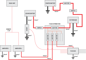
  • Can someone qualified reassure me that wiring as per this diagram is OK?
  • Do I need another fuse between the leisure battery and switch? It will be a very small cable run (15-20cm)
  • Also, if I take the ground side of the shunt, Victron and fuse box to a ground rail, what size cable would I need from the rail to the chasis? There's only a 10-15 amp load on the fusebox currently and fusebox is rated at a total of 100 amps.
Thanks

VAN ELECTRICS.png
 
You should fuse the cable from Starter to B2B at both ends ideally.

You should fuse the positive of the Leisure as close as you can to the terminal before anything else.

You would be better connecting the B2B directly to the Leisure (but through the fuse mentioned above) as it's important it gets an accurate voltage reading.

Consider if you need the switches. They do add more junctions to the circuits and opinion is divided if that introduces more failure points. Being able to isolate is good but you can also do that by making sure the fuses are accessible and not buried.
 
Agreed. You don’t have to have switches - you could just pull the fuse out to isolate.

Pete
 
@roadtripper
Why should you fuse the cable from the Starter battery to the Victron B2B input at both ends?
At the Starter battery it’s obvious and essential to limit the supply current and protect the cable, but what does an additional fuse add at the input to the B2B? What fault is it protecting against?
I personally would fuse the Victron B2B output to leisure battery cable at both ends as both are power sources: This is belt and braces though and also not strictly necessary IMHO as the Victron B2B is equipped with both output current limiting and short circuit protection, so again only the fuse at the leisure battery end is essential, unless I’m missing something.
 
@roadtripper
Ignoring the switch on the positive side of the LB, what difference would it make going from the charger via a fuse “direct” to the LB Vs. Going to the LB via a fuse in the distribution block?
 
Pulling midi anl fuses is a PITA and not being able to isolate quickly should something go wrong could have catastrophic consequences. Surely a switch is a good idea???
 
@roadtripper
Why should you fuse the cable from the Starter battery to the Victron B2B input at both ends?
At the Starter battery it’s obvious and essential to limit the supply current and protect the cable, but what does an additional fuse add at the input to the B2B? What fault is it protecting against?
I personally would fuse the Victron B2B output to leisure battery cable at both ends as both are power sources: This is belt and braces though and also not strictly necessary IMHO as the Victron B2B is equipped with both output current limiting and short circuit protection, so again only the fuse at the leisure battery end is essential, unless I’m missing something.
Because the Starter end will tend to be behind the battery or under the battery if you are using factory route, the fuse at the other end allows you to isolate the B2B in emergency or servicing without having to dig around the battery.

Remember fuses aren't just for safety, they have a secondary role for isolating circuits to work on.

It's also a bit of habit from basic relay wiring practice where it's possible for the relay to pull in/stick and energise the cable from the Leisure end. If you have reverse trickle chargers or dual output solar this can still happen.
 
Last edited:
  • Like
Reactions: EAN
Surely if it’s catastrophic then the fuse will blow ?

All my fuses are accessible, and when I need to isolate then it’s at my leisure, so far.

Pete
 
Pulling midi anl fuses is a PITA and not being able to isolate quickly should something go wrong could have catastrophic consequences. Surely a switch is a good idea???
As I say opinion differs. With high current 50A devices the additional junctions in the small switches you can get in a van can cause additional resistance and heating.

The main thing is to consider how you would isolate and do something that you're comfortable with and others in the van are aware of.

The only thing I would definitely recommend against is the turret type isolators with a key - often used as sports car ignition cutouts. I've seen far too many in the marine industry where they get stood on or knocked and if you break the turret off (which is relatively easy) you disconnect the circuit. Probably not so bad in a van but it's a serious issue in a yacht when you lose all your instruments or ability to start the engine.
 
@roadtripper
Ignoring the switch on the positive side of the LB, what difference would it make going from the charger via a fuse “direct” to the LB Vs. Going to the LB via a fuse in the distribution block?
Every junction is going to have a small resistance as is every fuse. Generally that's not an issue but when you are trying to sense the fractional voltages of a charging battery to control your charge profile it's best to keep them to a minimum.

Some B2B have a second very low current sense cable to deal with this and voltage drop. If you use this style of B2B it's less of an issue.

Personal preference is to have all your voltage sources at the same place in the circuit (as near as sensible) then feed through distribution fuse boxes. I'm not a fan of voltage sources at various places around the install if it's avoidable - likely to trip you or future owner up when you think something is completely isolated but you've only isolated it from one source not the other.
 
Cheers.
Anyone got any thoughts about cable size for shared Earth for ground side of the shunt, Victron and fuse box?
 
If you're using 16mm2 for all the new stuff I'd just use some of that.

What are your worst case loads?

Flat out charging the B2B is going to be drawing maybe 35A starter side and putting out 30A leisure side - but that 30A will be across the bus bar so only 35A via van ground.
 
Because the Starter end will tend to be behind the battery or under the battery if you are using factory route, the fuse at the other end allows you to isolate the B2B in emergency or servicing without having to dig around the battery.

Remember fuses aren't just for safety, they have a secondary role for isolating circuits to work on.

It's also a bit of habit from basic relay wiring practice where it's possible for the relay to pull in/stick and energise the cable from the Leisure end. If you have reverse trickle chargers or dual output solar this can still happen.

One question from the started battery to the leisure battery in the factory route is already fused (split charger)? so when we remove the split charge we need to add a fuse right?

If it is not the case, I guess it is better to fuse as close as possible to the battery terminal right?
 
One question from the started battery to the leisure battery in the factory route is already fused (split charger)? so when we remove the split charge we need to add a fuse right?

If it is not the case, I guess it is better to fuse as close as possible to the battery terminal right?
The factory feed to the split charger is fused at the Starter battery with a high rated fuse, yes, but you do need to add a smaller rated fuse to suit the B2B. My B2B (REDARC) specifies the input fuse rating to use.
I‘m doing my install now ,slowly, and will be adding my B2B input fuse where the factory feed from the starter battery ends at the split charge relay under the seat. It’s a convenient location, as I have to extend the cable at that point anyway.
 
Amps are max 80-90A max but in reality won’t ever be drawing anywhere near that. Fridge, lights, chargers 20-30A.
30A (Charger) + 30A (lights etc) would give me 50A headroom for Amps on a 110A cable. I think I’d need a fatter shared ground. Agreed?
 
As you say amps have high current to cope with dynamics, the sustained draw isn't going to be that level, likewise the draw the B2B puts on the van electrics isn't going to be 35 flat out unless you are regularly draining the battery. So unless you are planning on emptying the battery off grid and next day driving with the amps at PA levels I don't think you'll have an issue.

You don't say what your battery is but if you are genuinely going to have close to 110A draw then it will likely be flat in an hour, if you are drawing over 30A sustained then your B2B isn't going to keep up either. That seems unlikely?

If you're really concerned you have a bus bar, put two grounds in rather than one difficult to route one. I think at that point your issue will be the current capacity of the ground point.

A half way house might be to get everything done with a single 16mm2 but make sure your bus bar has a spare way. Have a good look at the data gathered by your shunt during some real world use as that will show most of the load, just mentally deduct say 40A as headroom for the supply of the B2B that it won't see.
 
Batt is 110ah lithium which should be more than enough for a bit of lighting and fridge in the circumstances that it will be used. I need to occasionally top up a laptop or tablet for the kids which will normally be done on journeys and doesn’t matter so much if the charger can’t quite keep up with the draw on the battery. The complication in my mind is with the amps as if they were to on average draw more than the charger puts out then I’m going to drain the battery even without anything else running. I’m now wondering whether I should run the amps off the starter battery as they are now. Only issue with this is that the max current of the amps plus the charger puts things close to or on the limit of the cable. I know in real terms the amps aren’t going to be close to 80-90A so not sure how much I have to worry here.

Could I install the shunt between amps and ground to get a view on what they typically use? It’d be a PITA as all the terminals are different sizes.
 
If they are existing amps and you were regularly drawing anywhere near 90 amps sustained I think you'd already be noticing some issues.

If you want to check now then get yourself a DC capable clamp meter, it'll be useful anyway with the sort of install you are doing and they are reasonable prices. I have the UNIT one:


Clamp it around either positive or negative for the amps and put something on at normal listening volume for you. I think you may be surprised how little it draws compared to the advised fuse. Start with the bass amp (I'm assuming that's how you've split them with 2) as that will be drawing the most.
 
@roadtripper Only the sub amp is connected to a speaker at the moment and it appears to be drawing less than 2.0A when measured at the amp and around 2.5A when measured at the battery. A bit difficult to get a steady reading due to the fluctuating nature of an amp, that I’m half upside down rooting under a seat, and it’s dark. I know you said I might be surprised at how little it draws but this is WAY lower than I might have guessed. Does it seem low to you?
 
Back
Top