B 2 B Ignition Feed?

Yes, that's ideal. Just make sure that you plug it in with cable facing towards the passenger side.
Sorry to be a pain with lots of questions
I read on the forums here that the centre line of fuses are ignition live. From the pic below is it the top circled fuses or the bottom bigger fuses that are ignition feeds on centre row of fuses
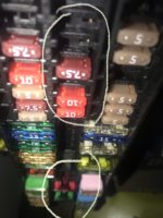
BDFA863F-43FC-4406-8536-0397FD9003B5.jpeg
 
Thanks buddy. Ill get on the search now then for a small bladed piggy back fuse.
I think i will go for a separate MPPT controller now as the CTEK is only 23v voc which means im roughly limited to a 150w solar panel. I wanted to fit a bigger panel tbh. Ill still use a CTEK for B2B charging thou. What are your thoughts guys ?
 
I think i will go for a separate MPPT controller now as the CTEK is only 23v voc which means im roughly limited to a 150w solar panel. I wanted to fit a bigger panel tbh. Ill still use a CTEK for B2B charging thou. What are your thoughts guys ?
Guys im going to start my electrics this weekend. Just wanted to know with these smart alternator setups, when it comes to reconnecting the main battery will it have to be reprogrammed ? Is there also any other issues that may arise once i reconnect, ie radio code etc
Regards Vee
 
Guys im going to start my electrics this weekend. Just wanted to know with these smart alternator setups, when it comes to reconnecting the main battery will it have to be reprogrammed ? Is there also any other issues that may arise once i reconnect, ie radio code etc
Regards Vee
No there is no issue reconnecting.
 
I think i will go for a separate MPPT controller now as the CTEK is only 23v voc which means im roughly limited to a 150w solar panel. I wanted to fit a bigger panel tbh.
Then put two 150s in parallel and you're still within the Ctel 20A/23v limits.
Cheers
Phil
 
Then put two 150s in parallel and you're still within the Ctel 20A/23v limits.
Cheers
Phil
so if i fitted 2 x 150w solars in parallel with the spec shown below it would work out at 17.6A and 21.1v ?? which would be under the spec of the CTEK


Solar panel specifications:

  • Peak power: 150W
  • Maximum power voltage: 17.0V
  • Maximum power current: 8.8A
  • Open circuit voltage: 21.1V
  • Short circuit current: 9.2A
  • Dimensions: 1389 x 673 x 2 mm
  • Weight: 3.3 kg
 
im also looking at this wiring diagram regarding the electrics in my van, replacing the VSR for a B2B. Does anyone see any problem with this setup or the thickness of wire used in this setup for a 12v system

campervan wiring diagram.jpg
 
so if i fitted 2 x 150w solars in parallel with the spec shown below it would work out at 17.6A and 21.1v ??
Indeedy, plus there are advantages to paralleling for example if one panel is in shade, then in a series arrangement the whole lot goes down, not so with parallel. Bear in mind that those are optimal panel specs - in practise you're unlikely to hit that mppt V & I sweet-spot unless you're camping on the equator! ;)
 
TravelVolts, I’m just curious about the reason for having the cable face towards the passenger side?
Because it won’t work if it’s fitted the other way round
 
im also looking at this wiring diagram regarding the electrics in my van, replacing the VSR for a B2B. Does anyone see any problem with this setup or the thickness of wire used in this setup for a 12v system

View attachment 60377
Be sure to change the 100 amp fuses for something more appropriate to your charger. Also note that this diagram does not show an earth bonding between the consumer unit and van body. There has to be one.
 
Here's the repair wire VW Audi Seat Skoda 000979009E Repair Wire Brand New | eBay

The pin is in the Black plug. Position 3 of the BCM under the dash. Pull the plug out, take the cover off and the two halves will slide apart. Click your wire in to slot 3, silde it together then pug it back in. It's just a tick box in VCDS have a look on the forum map for someone local to you with a yellow pin :thumbsup:
Anyone know if that is the right part number of repair wire to add a fuse to a spare position in the top centre row or is it better to just add a piggyback as above? Thanks.
 
Thanks chaps, piggy back it is then, probably much easier to fit!
A fuse box you can’t get your fingers in, what were they thinking :(
 
Anyone know if that is the right part number of repair wire to add a fuse to a spare position in the top centre row or is it better to just add a piggyback as above? Thanks.
I fitted a new terminal to the ignition switched area in the fuse box the other weekend. As said above, that repair wire you quoted is for the BCM.

What you need is a JPT (Junior Power Timer) crimp. The VW repair wire for a 2.8mm terminal, 1.0mm2 wire is 000979133E, and they seem to have a contact part number of N90684405. The difficult bit seems to be getting from the VW repair wire numbers to the actual crimp terminal part number (ie TE’s part number). From what I could find, for this it’s 927779.

I ordered this from Farnell:
https://uk.farnell.com/amp-te-connectivity/927779-3/crimp-contact-skt-17-20-awg/dp/2060345

Be warned though, fitting a new fuse box crimp terminal involved me taking the entire lower dash off. It took a long time just to eventually insert one crimped wire, but to me is a lot neater than a piggyback fuse holder.
 
Here's the repair wire VW Audi Seat Skoda 000979009E Repair Wire Brand New | eBay

The pin is in the Black plug. Position 3 of the BCM under the dash. Pull the plug out, take the cover off and the two halves will slide apart. Click your wire in to slot 3, silde it together then pug it back in. It's just a tick box in VCDS have a look on the forum map for someone local to you with a yellow pin :thumbsup:

I also tried fitting a BCM engine running signal wire the other weekend based on this repair wire part number. Are you sure this is correct?

VW repair wire 000979009E corresponds to a TE MQS contact (963715). But when I finally got to the BCM, it looks like pin 3 isn’t the smallest pin style on there, more like the next size up. Which from my searching, seems to be a MCP contact, possibly VW repair wire 000979025E.

Am I right that pin 3 on the BCM is not the smallest pin style on there? Or have I read the pin numbering wrongly?
 
Back
Top