B 2 B Ignition Feed?

Be sure to change the 100 amp fuses for something more appropriate to your charger. Also note that this diagram does not show an earth bonding between the consumer unit and van body. There has to be one.
thank you travelvolts
i am going to replace the wiring setup from the main vehicle battery to leisure battery from 16mm2 (110a) wire to 10mm2 (70a) wire and change the 100amp fuses for 30amp fuses. My reason for this is thinking that the wiring setup on the diagram i linked is a big overkill and such high amp is not needed as it wont draw that much. I will also be adding a earth bond to the consumer unit as you mentioned. i noticed this when i did my previous van.. do you think its ok to drop the wire and fuses to the amps i mention. i am going off advice from a electrician but i wanted to ask for a few opinions before doing this.. i am fitting the CTEKd250se charger to my system. if you have time would you mind taking a look at the manual for it i have linked
https://www.ctek.com/storage/ma/66f...7B39F70D1/SMARTPASS_120S-manual-low-UK-EN.pdf
thanks in advance
Vee
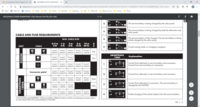
wiring dimensions for the CTEK rather than looking at the whole manual

2020-03-01 (14).png
 
Your chosen wiring and fuses are fine. I recommend using midi fuses for reliability. However, there is nothing wrong with using the 16 mm cable if it is already in place.
 
Your chosen wiring and fuses are fine. I recommend using midi fuses for reliability. However, there is nothing wrong with using the 16 mm cable if it is already in place.
i have no wiring in place atm buddy its a fresh install. i have already purchased 30amp midi fuses
thank you for all your advice
 
Here I just used (also for a CTEK d250 series) the feed that comes out under the (in LHD it's driver's side) passenger's side. It's a big cable that splits into smaller cables, and then attaches to a small fuse box under the seat. In the fuse box (in my case, depends on model and options) it feeds the 2 12v cigarette plugs in the back, so it was handy that those cables were already there and I just had to attach them to my new fuse box under the seat.

No faffing with extra cabling (that was for later, forgot how much cable a bit of an electricity installation eats, and how humans can fold in strange ways to reach some hidden spots in a car.....), cable is definitely big enough for B2B charger... .

Also have a 220v to 12v Bat charger installed under the other seat (CTEK). At the moment it's connected to the Aux battery. Was thinking of maybe changing it so my starter battery gets a recharge from time to time as well.... Suppose for the solar input it doesn't give enough (3,8V), so has to go the the starter battery itself instead then.. Although, not feeling very up to getting another cable to the front... :) . So that's for later...
 
On the website instructions for the Sterling Battery to Battery charger it says you should run a negative feed between each battery, is this necessary as most instructions on here for similar devices say a common earth will suffice?
 
On the website instructions for the Sterling Battery to Battery charger it says you should run a negative feed between each battery, is this necessary as most instructions on here for similar devices say a common earth will suffice?
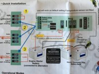
Have had a look at the instructions which came with mine see below, hope this helps

6E8FC0F2-7751-45D0-A3FA-D462ED032B14.jpeg
 
Yeah that's similar to the drawing i've seen but most other other diagrams for DC- DC chargers allow a common negative (Earth)
 
There’s a pin out on the BCM that does exactly this. Get the correct repair wire and push it into the empty slot. You’d need VCDS to code that you have an AUX battery fitted but this will do what you want. I use it on mine. The charging light on my B2B doesn’t come on until the engine has been running for a few seconds. When stop start kicks in the light goes out.
Have you got the pin location for this please
 
Hi Pauly,

This is what Schaultd emailed me when I asked if I could use just an ignition on feed:

"You must have any signal 12…14V which is high when the motor is running.
In case you have a flat starter battery and like to start the motor and… the ignition signal is already on the booster will take 25A from the battery out additional. I think better to have a signal which is comeing up when the alternator is already on."


So, it looks like you do - or the leisure battery takes the starter load (Travelvolts mentions this I think in his posts also) and what is odd is that there is no information 'anywhere' that states clearly how to do this. Yet everyone who has blue motion with regeneration braking (all T6's?) must need to do it as the battery is kept low to allow for the regen to top it up (and this is not the stop start but that clearly makes it more important as will stress the battery/wires more often), and as I understand the factory fitted lesure battery has such a feed from the BCM under the seat.

This is why I have spent weeks trying to find an answer . There must be an answer from the professional fitters?

Or is another unit better - is there a manufacturer that has a clever sensor that knows when engine is running (some sort of voltage check with delayed start?) or one that cleverly prevents surges back in opposite direction (to main battery)??
cheers JP
 
Just Installed the Renogy 50a dc-dc charger under passenger seat and pretty much done but now need i to connect the red ignition live wire from charger to an ign live, for the smart alternator. T6 2018
I’ve looked and found a relevant post regards tapping into fuse box under gear lever in cab but seems a mine field when reading
Can anyone offer a noddy guide on where exactly to connect it and how, not great knowledge on electrics.
Do I just find an existing ignition live fuse and tap into it on a piggy back cable or do I use a spare slot and if so what fuse to use
Seems like thread indicates to go for top centre row

Not removed dash covers to look yet. Tomorrow hopefully
Any help appreciated
 
I just bought the piggy back fuse from Amazon and placed it in the middle row of fuses,
I bought four so if you need one i’ll post to you but please check first
Bob
 
I just bought the piggy back fuse from Amazon and placed it in the middle row of fuses,
I bought four so if you need one i’ll post to you but please check first
Bob
Thanks for the offer and info, appreciated but I’ll just get one local. What fuse do you use for it. Have you installed it and all good
Thinking about it, I’m sure that’s where they installed my dash cam so will have a look tomorrow. Makes better sense now

Just Found a good post that explains it -
 
Last edited:
I used a micro fuse piggyback from Halfords. I recall someone on here suggesting the middle row of the fuse box under the middle of the dash. Run the red cable under the cab mat and under the plastic trim into the fusebox. It's very simple. Good luck.
 
Back
Top