You'll be exchanging WiFi passwords for beers at T6F events I'm assuming 


now there's an idea. - 24hr access per can. ( no speed guarantees offered )You'll be exchanging WiFi passwords for beers at T6F events I'm assuming

@Dellmassive - Thanks for the info Lee. A lot of info to take in, for me.ok @BoroBoy
this is the plan. . .
Fag Packet schematic to start with :
its all based around the 6way USB box, powered from the LB 24/7 - https://amzn.to/3VvagmT
well have:
2x USB C cables hardwired for the phones - https://amzn.to/4bOKU9d
1x USB 3 extension port in the glovebox - https://amzn.to/4e8oMbr
1x USB 3 extension to the A-Pillar ( for the mini WIFI stick) - https://amzn.to/3VvG0rT
1x WIFI USB Huawei with EXT annt - https://amzn.to/3X7QtLz
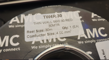
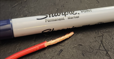
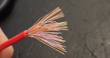
then well have the new 4mm2/39A feed to the rear D-pillar area, to run: - Single Core Thin Wall Cable - 4.0mm² 39A
2x 12v reading lamps - 12v Switched 140mm Flexible LED Reading Light - Warm White (Multiple Colour Options)
4x 12v roof lights - 12v 69mm Flush LED Spotlight - Multiple Colour Options + Dimmable
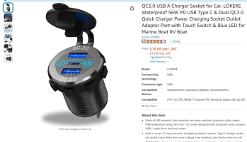
2x USB C/PD panel charge point with ON/OFF button. - https://amzn.to/3Vb16dX
and separate will have the Super Mega Wifi Box. (that will be used for being OUT-OUT ie camping & festivals)
View attachment 244808
++++++++++++++++
so this 6way USB box, will power it all..
View attachment 244809
+++
well use these quality cables to get to where we need them. . .
View attachment 244810
doing the same as we did on the other van. . . but ill hardwire in the power this time to the LB.
- 12v Feeds:
- Ignition Live Under Passenger Seat -- How It's Done --
- Installing 12v Sockets -- How It's Done --
- 12v Ignition Feed + 5xusb Charging From Ign Feed -- How I Done It --
- 12v Aux Feed + 5xusb Charging From Aux Battery -- How I Done It --
View attachment 244811
++
then well swap out the existing roof lights for these dimmable ones.
View attachment 244813
++
well run a new fused feed to the rear, and use the chassis as the NEG.
with this cable,
View attachment 244815
++
and fit these new 12v lamps at the rear D-pillar. .
View attachment 244812
+++
and also add these USB panel chargers. . .
View attachment 244814
as for the WIFI . .
ill be fitting this USB Huawei mini router for the main normal 24/7 van wifi ( same as the other van)
prob behind or on the A-pillar post cover.
but it will be plug N play, - so that i can swap it out for the super mega wifi.
View attachment 244816
+++
then when its camping or festival time. .
ill swap the SIM card from above to the Big Boy WIFI box . - Teltonika RUT951 150 Mbps, 4-Port Dual-SIM 4G LTE Router - Unlocked | eBay
View attachment 244817
we also went so this bad boy antenna . . - Poynting PUCK-5 Antenna | NetXL
View attachment 244818
+++
as for the SIM for the Above, im using these SMARTY SIMs, £8 a month 50Gb on a 30day rolling contract.
here's my referral link to get yourself one with £10 credit for us both !!! - Happy days.
View attachment 244819
.
i run the small USB on the VAN, been on there since 2018 - still going strong. - Van WIFI & Mobile Data -- How I Done It --@Dellmassive - Thanks for the info Lee. A lot of info to take in, for me.
I already have a Smarty data only deal at the moment.
I will be interested to see how the WiFi set up is.


just done it today. . . . stay tuned for the full install.Did you cover your Ablemail AMT12-2 wiring @Dellmassive or did I miss it? Just trying to work out where to plumb mine into the aux battery side, will it be OK to go into your 12v fuse box?
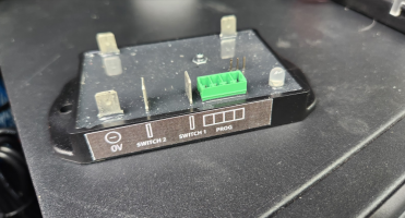
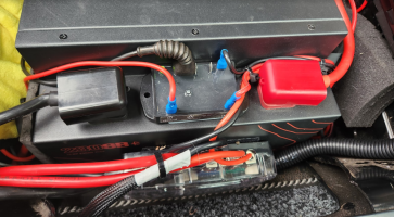

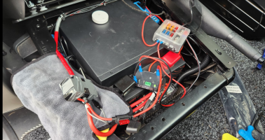
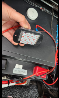

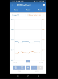
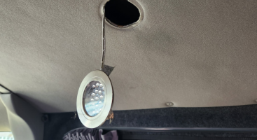


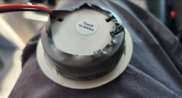


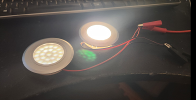
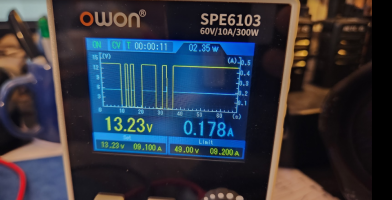

That's really curious, I wonder where the power is going? I know some cheap night light circuits just short out the led to dim them but they tend to be mains powered so they don't care about efficiency, I'd expect those to be using PWM178mA each @ 13.2v (interestingly they draw the same current over the whole dim range)
12v LB Feed to the Rear D-Pillar.Moving the rear load area LED lights over to the LB. . .
the previous owner fitted roof LED lights - which was nice.
and added this 20mm three way rocker switch, lovely.
that basically simulated the OEM three way switch in the rear. . .
we have:
II - OEM curtsey lighst
0 - OEM OFF
I - OEM ON with 15min timer
View attachment 244414View attachment 244426
which basically is the same as factory switches. . . . but this was running my starter battery flat.
more info here - LED Interior Cargo Lights - How I Done It.
***************************************************************************************
Factory Non-LED 3 wire setup:
(brown) - earth point left a-pilar
(brown/red) - connection 1 main harness (BCM switched neg 0v)
(red/black) - positive connection 1 main harness (BCM timed +12v) ( 7.5A fuse 24 holder C)
****************************************************************************************
Factory LED 2 wire setup:
(brown/red) - connection 1 main harness (BCM switched neg)
(red/black) - positive connection 1 main harness (BCM timed +12v)( 7.5A fuse 19 holder C)
****************************************************************************************
lets see how they done it. . .
pulling the headlining we have the three wires. . .
View attachment 244416
that go up tio the top of the B-pillar,
where they handily connect to the four LED light, sweet.
View attachment 244417
tracing them back we can see that they just used the OEM three wires and from the front light and pulled them forwards. . .
View attachment 244419
ok, job done,
so all i need to do is replace the OEM timed starter battery POS with a 24/7 LB feed. . .
im also planning on adding some USB chargers to the B-pillar,
so ill run a nice beefy cable from the LB fuse box, and run the lights + other stuff.
i found some of this stuff. . .
View attachment 244422
a nice fat bit of copper twin,. . .
View attachment 244423
i run it from the top of the B-pillar,
down to the floor matt. . .
View attachment 244424
then along the floor between the two mat joins. . . ( check out that crud + sand under the flooring, Yuck!!! )
View attachment 244425
over to the drivers side, the up into the seatbase, and connected to the small 12v fusebox. .
switching on the rear lights, we now see 1A being drawn from the LB, where before it was coming from the starte battery. . .
a nice easy fix. . .
View attachment 244427
following the cable back up to the lights, we can see the same 1A going direct to the 4x LED lights,
so 250mA each . .
View attachment 244428
this is also varified on the newley fitted Vic SHUNT. . . now showing a 1A load being drawn.
View attachment 244429
obviously some clips got broken . . . . so anyone know where to get some of these from that are not total pants and just snap by looking at them>?
roof join bar:
View attachment 244430
B-Pillar top - long
View attachment 244431
B-Pillar white - short.
View attachment 244432
.
once again all back together. . . . now light LB powered lights. . .
View attachment 244433
.










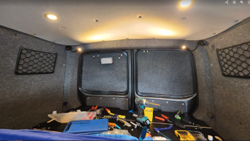


nice work. always appreciate your write ups, helps us mere mortals learn something!!12v USB Chargers and 12v reading lights - Rear D-Pillar.
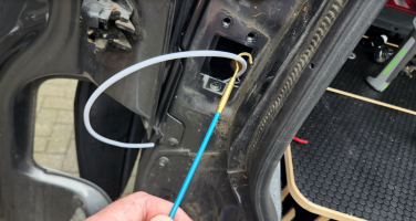
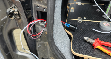
fish cable,
crimp ends
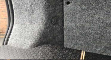
screw in charger. . .
View attachment 245029
View attachment 245030
.
View attachment 245032
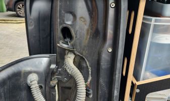
pulling the panels back enough to fish the cables around. . .
nice to see the efforts of the previous owner with the sound deadening and heat insulation. . .
View attachment 245031
we decided we wanted these 12v reading lights up on the top corners,
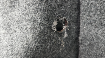
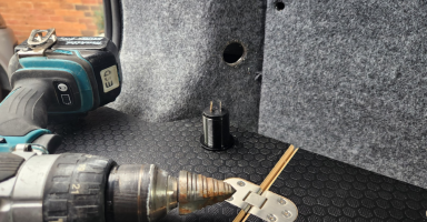
so drilled a small 8mm hole and run a length of 1mm twin core from the light fitting to the pillar void.
View attachment 245033
then used self drilling metal screws to drill and fix the lamp in place.
the area felt double skinned.
View attachment 245034
we run the same 4mm2 red power cable up and over the rear roof - following the OEM cable loom, to get power to the other side. . .
i used seperate NEGs direct to the chassis at the lower D-pillar / side panel. . .
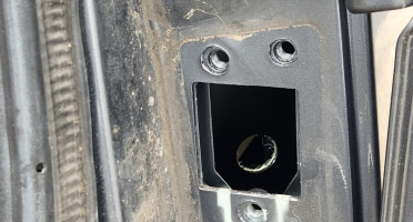
there was already some holes. . . so i exposed some clean metal and used some ring terminals and self drill screws to make a good clean NEG connection. . .
View attachment 245035
a quick test gave us this. . . .
View attachment 245036View attachment 245037
so thats the reading lights, USB chargers, interior lights sorted. . .
then i done the AMT12-2 starter trickle charger shown above.
View attachment 245038
++++++
so next will be back onto the 6way USB charger and WIFI.
++++++
.
not sure, they must be bleeding it off as heat?That's really curious, I wonder where the power is going? I know some cheap night light circuits just short out the led to dim them but they tend to be mains powered so they don't care about efficiency, I'd expect those to be using PWM
Well second night with the new lamps,Swapping out the internal rear LED lights. .
we had the previous cool blue, lights, they were super bright at night and needed to crawl out of bed to get to the light switch to turn them off.
so we decided to swap them out for the touch dimmable warm white jobs. . .
these were the old ones that we had. . .
View attachment 244990View attachment 244993
so i just cut switch off, cut the wires, and used a multimeter to check which was POS and NEG.
then connected the new lamp with some chock block.
View attachment 244992
a quick test showed they worked. . .
but they when pressing in the hole, they was very loose and fell out.
so a quick wrap around with some tape made them wider, so they fit snug.
View attachment 244994View attachment 244995
nice. . .
View attachment 244996
before we had this cool blue. . .
View attachment 244997
and now we have this warm white. . .
View attachment 244998
all four swapped out and working ok.
+++++++++
id previously tested these at home on the bench supply, so specifically tested if they remembered the last setting. . .
ie:
ON
OFF
DIMMED
FULL BRIGHTNESS
which they did, even with the PSU off for 24hrs.
i say this now, as last night the first night out, i was sure they were left on high, but when we come out the place later that night they seemed to be on full dimmed?
but it was a family party and id had a few juices - so was in no fit state to look into anything.
retest later.
following from the above we have on the switch:
I - On as curtesy with door + fade (Fed from LB but NEG via BCM)
0 - Off
II - ON 24/7 fed from LB
+++++++++
Bench test:
178mA each @ 13.2v (interestingly they draw the same current over the whole dim range)
View attachment 244999View attachment 245000View attachment 245001
.
Swapping out the internal rear LED lights. .
we had the previous cool blue, lights, they were super bright at night and needed to crawl out of bed to get to the light switch to turn them off.
so we decided to swap them out for the touch dimmable warm white jobs. . .
these were the old ones that we had. . .
View attachment 244990View attachment 244993
so i just cut switch off, cut the wires, and used a multimeter to check which was POS and NEG.
then connected the new lamp with some chock block.
View attachment 244992
a quick test showed they worked. . .
but they when pressing in the hole, they was very loose and fell out.
so a quick wrap around with some tape made them wider, so they fit snug.
View attachment 244994View attachment 244995
nice. . .
View attachment 244996
before we had this cool blue. . .
View attachment 244997
and now we have this warm white. . .
View attachment 244998
all four swapped out and working ok.
+++++++++
id previously tested these at home on the bench supply, so specifically tested if they remembered the last setting. . .
ie:
ON
OFF
DIMMED
FULL BRIGHTNESS
which they did, even with the PSU off for 24hrs.
i say this now, as last night the first night out, i was sure they were left on high, but when we come out the place later that night they seemed to be on full dimmed?
but it was a family party and id had a few juices - so was in no fit state to look into anything.
retest later.
following from the above we have on the switch:
I - On as curtesy with door + fade (Fed from LB but NEG via BCM)
0 - Off
II - ON 24/7 fed from LB
+++++++++
Bench test:
178mA each @ 13.2v (interestingly they draw the same current over the whole dim range)
View attachment 244999View attachment 245000View attachment 245001
@Dellmassive - 2nd photo. Is that the bluetooth device connected to your AMT trickle charger? Does the ABB 07 just allow monitoring or can it allow remote setting of the trickle charger pulsing settings?
.

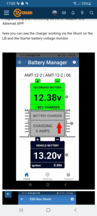

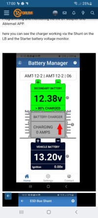
Sounds good. I will look at getting one.@BoroBoy
It allows the changing of individual settings, as well as live view.
I'll get some screenshots.
I think the program settings 1-4,5-8 change numerous settings.
You can get to the settings with the remote.
But there isn't the option to select preset, just separate settings.
Not essentials, I just used it as I had it.
Just come out to the van for another test on the third day.Well second night with the new lamps,
And another family gathering for another birthday.
And once again the rear lights come on fully dimmed?... But I'd left them all on fully bright?
I know they bench tested ok over a 24hr slot.
So it must be something to do with the switch position when left on the bcm for curtisy lights.?
The new 12v power is direct from the LB.
And the ground is via chassis.
So something must be going on when the bcm goes to sleep causing the lamps to loose the setting and go to dimmer mode?
I could try moving the POS back to the OEM supply? As a test.
i could try leaving them on the manual off as a test?
Try different lamps?
..
Not sure.
Anyone else got these dimmer lamps? .... On the leisure battery.
.
