12v USB power supply for Cab area + WIFI feed.
.
getting back on track, we have this kit in stock now.
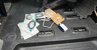
I've used BESTEK before and find there small 300W Pure Sine Inverter great,
so had no problem ordering this mini 6way USB power supply.
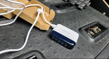
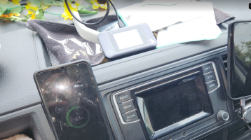
plugging it in for a quick test in the 12v dash socket, , , with the phone and tempory MIFI box,
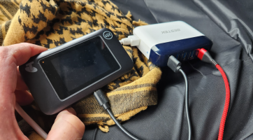
the ports show two charge speeds, ,
QC3.0 in the top two A ports, and AUTO 0-2.4A in the lower three A ports. ( the very top is USB-C PD)
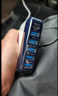
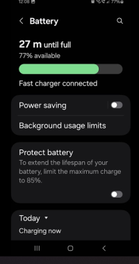
testing with the phone, we see "charger connected" in the standard ports,
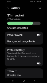
and "FAST charger connected" to the QC3 ports, - so well be using these for the main two phone charge leads, as they will charge faster.
+++
1st step was to remove the Glovebox, DC fusebox cover and end cap,
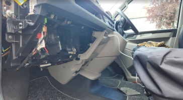
and the lower cover. . .

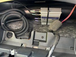
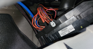
we are looking to locate the USB charger unit behind this trim as there is loads of space. . . . it will be tucked away behind and to the side of the SC fusebox.
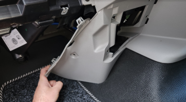
loads of space back there, though it doesnt look like it from this pic. . . .
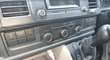
i removed the vent and radio trim next. . .
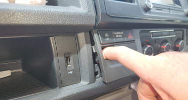
i find it easiest to pop out these blanks with a trim tool, then gently pull out to pop the clips.
then work your way around with the tool . . . .
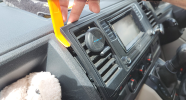
eventually you end up with this, which gets you loads of access around the dash. . .
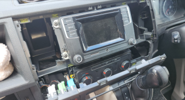
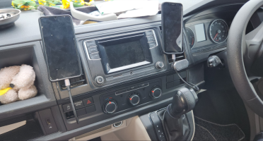
i fished up a 1M USB-A to C lead to the LEFT and a 2M USB-A to C lead to the RIGHT
(ill be cutting holes in the blanks and replacing them after.)
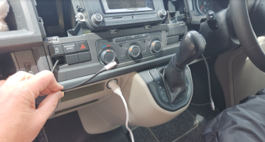
i used a 2M USB-C 3.0 extension lead to the glovebox area. . . .
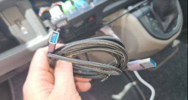
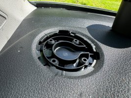
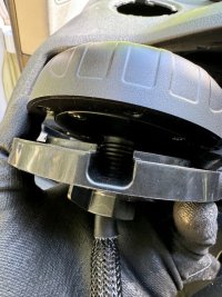
which will come through this black cap here . . . . i think its for USB port or the OEM torch location? cant remember ATM, but it very handy to get a USB lead into the glovebox)
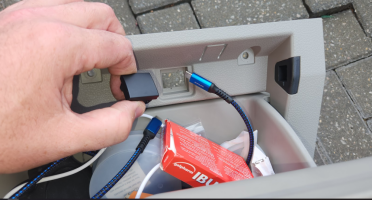
and ill fit a 3M USB-C 3.0 extension cable for the WIFI up to the A-pillar,
but i then realised that the van had the A-pillar grab handles. . . so ill carry on up too the centre roof line by the mirror.
my original idea was to the the WIFI stick plugged in behind the A-pillar plastics as they pop off super easy. . .
but that's now not an option as the grad handles are bolted in.
so plan B is to just plug it in, in the glovebox link cable (worked fine in the VAN for years)
or
Plan C is to plug it in, centre top windscreen, which will give it better reception and range. . .
so well take the leads from the footwell,
up being the glovebox to the corner of the windscreen, up the A-pillar. .
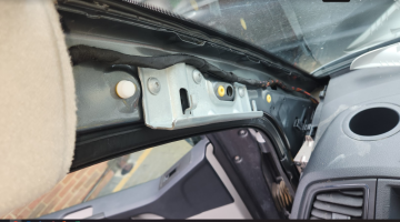
and tucked in over to the centre, with the slack pushed into the roof void.

...
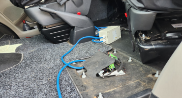
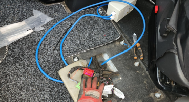
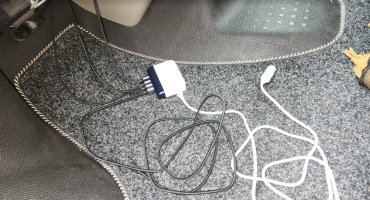
the result is this. . . . . all the leads plugged in at the footwell area.
Pic limit . . . .
TBC:
.
.
getting back on track, we have this kit in stock now.

I've used BESTEK before and find there small 300W Pure Sine Inverter great,
so had no problem ordering this mini 6way USB power supply.

plugging it in for a quick test in the 12v dash socket, , , with the phone and tempory MIFI box,

the ports show two charge speeds, ,
QC3.0 in the top two A ports, and AUTO 0-2.4A in the lower three A ports. ( the very top is USB-C PD)

testing with the phone, we see "charger connected" in the standard ports,

and "FAST charger connected" to the QC3 ports, - so well be using these for the main two phone charge leads, as they will charge faster.

+++
1st step was to remove the Glovebox, DC fusebox cover and end cap,

and the lower cover. . .

we are looking to locate the USB charger unit behind this trim as there is loads of space. . . . it will be tucked away behind and to the side of the SC fusebox.

loads of space back there, though it doesnt look like it from this pic. . . .

i removed the vent and radio trim next. . .

i find it easiest to pop out these blanks with a trim tool, then gently pull out to pop the clips.

then work your way around with the tool . . . .

eventually you end up with this, which gets you loads of access around the dash. . .

i fished up a 1M USB-A to C lead to the LEFT and a 2M USB-A to C lead to the RIGHT
(ill be cutting holes in the blanks and replacing them after.)

i used a 2M USB-C 3.0 extension lead to the glovebox area. . . .

which will come through this black cap here . . . . i think its for USB port or the OEM torch location? cant remember ATM, but it very handy to get a USB lead into the glovebox)

and ill fit a 3M USB-C 3.0 extension cable for the WIFI up to the A-pillar,
but i then realised that the van had the A-pillar grab handles. . . so ill carry on up too the centre roof line by the mirror.
my original idea was to the the WIFI stick plugged in behind the A-pillar plastics as they pop off super easy. . .
but that's now not an option as the grad handles are bolted in.
so plan B is to just plug it in, in the glovebox link cable (worked fine in the VAN for years)
or
Plan C is to plug it in, centre top windscreen, which will give it better reception and range. . .
so well take the leads from the footwell,
up being the glovebox to the corner of the windscreen, up the A-pillar. .

and tucked in over to the centre, with the slack pushed into the roof void.

...
the result is this. . . . . all the leads plugged in at the footwell area.

Pic limit . . . .
TBC:
.
Last edited:

