Diagrams, Schematics & Wires -- How I Done It --

Dellmassive

T32 204 DSG LWB SLN PV MY18 & T30 SWB KMB MY67
VCDS User
Moderator
VIP Member
T6 Master
Diagrams, Schematics & Wires -- How I Done It --


**************************************************
Dellmassive`s -- "how I Done It" -- Thread
**************************************************
Kit List And Stuff -- How I Done It & What I Use --
**************************************************

This is a handy place to post my -- How I Done It -- Diagrams and schematics etc.


To start thing off here is todays diagram,


Using speaker ISO connectors and breakout loom:


AMP Connection.jpg
.
.
.
.
.
.
.
.
.
.
 
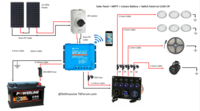
Solar Panel + MPPT + Leisure Battery + Switch Panel on LOAD OP

Here we have a basic schematic, the Solar Panel via the MPPT will charge the leisure battery. The loads are connected via the MPPT LOAD OUTPUT so that if the battery power drops below a set point the LOAD OP will shut off protecting the battery.

EDIT: fuse-box feed cable now down-rated 6-10mm (but fused at 30A)


upload_2020-1-25_14-3-14.png

.
 

Attachments

  • Solar Panel + MPPT + Battery.pdf
    222.2 KB · Views: 326
Last edited:
- Leisure Battery & DC-DC with integrated MPPT & BM2 Monitors -

- Here we have a Redarc 50A DC-DC connected to a leisure battery, (charge Aux Batt when engine running)
- we are also connecting in the Solar PV (charge Aux batt 24/7 when sunny)
- And running loads direct from Aux Battery,
- Using 2x BM2 battery monitors (one on each battery)

upload_2020-1-3_13-19-41.png

.

*************************************************************************************
Aux Battery with seperate DC-DC & MPPT controllers

- Here we have a Redarc 50A DC-DC connected to a AUX battery, (charge Aux Batt when engine running)
- Solar PV on a Victron MPPT (charge Aux batt 24/7 when sunny)
- And running loads direct from Aux Battery,
- Using 2x BM2 battery monitoring APP (one on each battery)
- Using Victron MPPT monitoring APP


upload_2020-1-3_13-46-11.png


...


***************************************************************************************************
 

Attachments

  • T6F DC-DC.pdf
    229.9 KB · Views: 309
  • T6F PP DC-DC - mppt .pdf
    217.6 KB · Views: 199
Last edited:
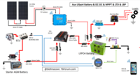
- Aux Lifpo4 Battery & DC-DC & MPPT & LTD & LBP -


Here we have a LifPO4 battery setup.
The DC-DC charges when engine running.
The MPPT charges when sunny outside,
Lifepo4 LTD (low temp disconnect) of DC-DC via BMV712 relay contacts.
Lifepo4 LTD (low temp disconnect) of MPPT via BMV712 Temp sensor and VE-Direct.
Lifepo4 LBP (Low battery protect) via Victron 100A Smart battery protect.

****************************************************************************************

upload_2020-1-3_17-42-16.png

.

**********************************************************************************************

next


**********************************************************************************************
 

Attachments

  • T6F PP lifpo4 + ltp.pdf
    233.6 KB · Views: 135
Last edited:
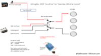
LED Lights, DPDT “on-off-on” for “Override-OFF-BCM control”

upload_2020-1-6_11-57-31.png
 

Attachments

  • T6F PP led lights rear dpdt.pdf
    133.8 KB · Views: 183
Interesting. Would this stop the 'glow' of the LEDs?
only in the OFF position....

for all other cases try the @Deaky trick 1k/3K/5K/10K ohm

credits: @Deaky

(2W 2Watt Power Superior Metal Film Resistor 1% Tolerance 1ohm to 2.2Mohm)

EDIT - its been tested out that due to differences in BCM`s and manufacturer setups that the value of the resistor may need to me adjusted.
example, if the LED`s still glow dimly when a 1K resistor is used try other values, also if a 1K resistor gets warm when the LEDs are on try upping the value.

to test . . . just fit the resistor across one of the LED lights and test. (only one should ne nessassary)


circuit-png.52940


If your connected to the courtesy circuit then +12v will be the red/black wire and -ve will be brown/red wire


Led Light Glow Courtesy Setting.


@Deaky : These are the ones I used - 2W metal film resistor - 1k , 2k, 3k, 4k, 5k, 10k


*******************

edit: @travelvolts


1587375781129.png

If all else fails run a supply from your leisure battery to your LEDs via a relay controlled by a 3 position switch. Centre off, pos 1 for on on demand and position 2 for courtesy switching. So, LED neg to centre pin of switch. The two outer pins connect to brown and brown/red. You will need a small electrolytic capacitor across the relay coil to stop it buzzing during fade out and a diode between the supply and the cap to stop the lights from draining the cap down. I use a 1000uF 16 volt one.
The object of the exercise is to isolate the switched negative from the LEDs.


****
 
Last edited:
A quick one to be sure. If we are taking a wire from leisure battery to two cbe fuse boards (so that is two lots of the four spade fuses) what thickness cable would you suggest? 10mm?? Seems pretty chunky.

running off the fuses are led lights and also 3 x 12v sockets. One will have a fridge plugged in (dometic cool box type)
it depends on what power you plan on drawing . . .


you say 3 x 12v sockets . . . . but if you plugged a 12v tyre pump in you could draw 10amps or more, so the diagram shows the thicker wires to account for that.


if your referring to this diag . . .

upload_2020-1-23_21-59-2.png


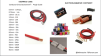
if your just using low amp stuff you could use thinner cable . . . have a look at these:

***********

Kit List And Stuff -- How I Done It & What I Use --

***********

rough ratings are:

  • High temperature thin wall low voltage cables suitable for use in the automotive, marine and allied industries - Comes as a 10m loose coil
  • Manufactured in accordance with ISO6722-1:2011 (Class B) 105°C
  • Suitable for 12v and 24v systems (Maximum voltage 60v)
  • Conductor Cross Section(mm²) - 0.5mm - 11Amps, 0.75mm - 14Amps. 1.0mm - 16.5Amps, 1.5mm - 21Amps, 2.0mm - 25Amps, 2.5mm - 28Amps
  • Plain Copper Conductors to BS EN 60228:2005 - PVC Insulated
**************

so maybe look at the 2.5mm(28amp) https://amzn.to/36i7WD3 for short runs,

increase the cable size for longer runs.


************

Twin cable (Flat 2 Core 1.5mm² 21Amps, 5 Metres) 5Metre - https://amzn.to/35V5nY4

Twin cable (Flat 2 Core 2.0mm² 25Amps, 5 Metres) - https://amzn.to/393hDYp

Twin cable (Flat 2 Core 3.0mm² 33Amps, 5 Metres) - https://amzn.to/377qV41

Round Twin 2 Core Cable 12v 24v Thin Wall Wire (25 AMP Rated 2mm²) 10 Metre - https://amzn.to/393hGU5

Single cable 1.5mm² - Car Electrical Wire, Set of 2 Colours (Red/Black) at 5m - https://amzn.to/2MnDhx4

Single cable 2.5mm² - Car Electrical Wire, Set of 2 Colours (Red/Black) at 5m - https://amzn.to/2MnhDIZ

6 Way Blade Fuse Box with LED Indicator for Car Boat Van - https://amzn.to/2sSFCcr

12 Way Blade Fuse Box/Bus Bar With Cover - https://amzn.to/2MmWtec

5 Gang Toggle Switch Panel, Dual USB Socket Charger 12V Power Outlet LED Voltmeter -
https://amzn.to/35MsHqV

.
 
I would run 1 x 6 mm tri rated cable to each fuse box and spread the load. Fuse each cable at 30 amps and have say, two sockets on one fuse box with the LEDs and one socket on the other fuse box with a USB. This way the load on each fuse box should never exceed 25 amp absolute max. The problem with using 10 mm on these fuse boxes is trying to get the cable terminated correctly to suit and the mechanical stress of heavy cable on what is after all just a PC board.
I do a ready fused 5 metre cable suitable for the job https://www.travelvolts.net/product-page/fused-6-mm-cable
 
Hi, thank you. That kind of confirms my thinking as well. I'll order two of your cables.

Another question. Would you suggest taking the negatives back to the battery rather then earthing on the vehicle? Does it in anyway effect the leisure v starter battery relationship?
 
It is fine to use body earths with the proviso that they are of good quality and remain accessible for future fault finding. No self tappers please! If you can get to VW earth points, great.
 
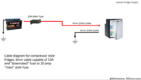
Leisure Battery & Fridge:

upload_2020-1-25_13-25-46.png
 

Attachments

  • T6F PP Leisure fridge.pdf
    106.6 KB · Views: 94
If all else fails run a supply from your leisure battery to your LEDs via a relay controlled by a 3 position switch. Centre off, pos 1 for on on demand and position 2 for courtesy switching. So, LED neg to centre pin of switch. The two outer pins connect to brown and brown/red. You will need a small electrolytic capacitor across the relay coil to stop it buzzing during fade out and a diode between the supply and the cap to stop the lights from draining the cap down. I use a 1000uF 16 volt one.
The object of the exercise is to isolate the switched negative from the LEDs.

You can avoid the relay buzzing and the faint glow of the leds issues by using a MOSFET switch module instead. I have been playing with a combination of a suitable MOSFET switch and a remote switch/dimmer module as someone was looking to do this before Xmas, and the right MOSFET module arrived today. Took a while to find one that had the input completely isolated and which switched the negative supply line output so I could parallel it up with the Dimmer unit, (also a MOSFET switch) but I've tested out in the van today and all seems to work ok. As the MOSFET switch was only £2.75 it's at least as cheap as a relay. And as it's a MOSFET switch the LEDs dim and brighten in the sme way as the van Courtesy Lights do.
 

Attachments

  • Adding remote dimmable LED lights.pdf
    156 KB · Views: 192
Back
Top