Fiamma Aqua 8 issue or installation issue?

from above re accumulator/expansion tank:


What pressure should it is set to?
Our tanks come pre pressurised to go with the calorifier. If you need to change this then it should be set to a pressure above your pump pressure but below the pressure release valve cut out pressure. This is very important or the expansion tank wont work properly.

.
OK, so something between 1.5bar and 3Bar.
This would indicate that having a pressure in the system above the water pump rated pressure will not be a problem.
 
the installed parts seem to match up and look ok.

so lets look at the Pump power feed.

a poor feed will cause high resistance, that will cause high currant and issues.

the 10Ltrs pump above states 12vdc @ 3.4A . .

lets look at the connections for your power and ground? - get some pics?

where is the feed coming from?

where is the ground?

can you get a volt meter and get a volt reading accross the pump when - static, no engine.?

can you get a volt meter and get a volt reading accross the pump when - static with engine running.?

can you get a volt meter and get a volt reading accross the pump when - pump running , no engine.?

can you get a volt meter and get a volt reading accross the pump when - pump running with engine running. ?

a restistance reading from the pump NEG lead doWN TO different ground point.?

All good investigative options, which I will explain;
The feed is good, I have a +ve and -ve direct feed to the CBE PC104 unit with 13.7v showing at the pump connection. This is protected within the CBE unit by a dedicated 5Amp fuse.
I checked the -ve feed against a direct ground and the results are the same.
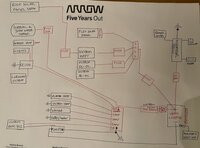
Here's my wiring sketch;
IMG_4669.jpeg

I checked the pump for open circuit, all OK.
Plugged it back in and switch on again, low and behold it fires back up again.
The last time I opened the tap I had hot water in the tank and opened the hot, this was when it failed.
(I've just noticed an error in my diagram above, not relatedo_O)

Plan;
Reduce the expansion tank to 2Bar of pressure.
Disconnect hot water tank from pump and run a pipe into a bucket. Heat water and make sure there's now leaking pressure back through the system.
Run just on cold for the next few weeks to make sure that side is all tickety-boo.

When testing again just now, the pump is definitely having to work harder on the hot side, (not heated), possibly due to the energy required to push past the Non-Return Valve.

Thanks again for all the attention on this!

Regards
Ollie.
 
Last edited:
electrical layout looks good. . .

i was going to suggest to remove and cap off the red expansion tank for a while and do some testing to try and narrow down the fault.

the pump above seems to just be a very simple dc motor with a pressure switch, so not much to go wrong?( brushes and switch)

may be get clamp tester and start metering out the current draw?

when the pump is pushing against higher pressure it will have to work harder due to mechanical resistance?

keep us posted with the results of the testing. . . .


for next testing stage - get one of these:


.

1616651247681.png
 
That's what I thought. There must be a diaphragm in the expansion tank between the water part, (at the bottom) and the air at the top. The question is does this exert any back pressure to the pump. You can see from the instructions there is a non-return valve built into the heater, again I would assume this would protect the water pump from that back pressure and when you open the tap the 'excess' hot water pressure will exit there.
The NRV separating the cold feed from the pump and the hot water system has a spring. The answer to your question is for the pump to deliver cold water to the hot water system it has to overcome the NRV spring rate (low force) and the hot water system pressure. If the hot water system pressure is higher than 1.5 Bar due to thermal expansion into the expansion vessel the cold pump will not run as the pressure switch trips it out, it will however operate on demand to supply the cold tap.
The cold water delivered by the pump to the hot water system will be between the pressure required to open the NRV and the max pump pressure of 1.5 Bar.
With no flow through the hot system the pump will trip out on the pressure switch and the NRV close when the NRV spring and hot water system pressure act against the cold water system pressure.
When the water is heated as the water in the expansion vessel cannot be compressed but the air in the expansion vessel can the expansion vessel bladder deflects pressurising the air further, the hot water pressure will be exactly the same as the air pressure.
The additional benefit of the expansion vessel is that it acts as an accumulator and will provide a slightly greater volume of hot water on demand plus reduce the pump cycles.
The water pump pressure switch will have two set points; start and stop, obviously if they are set too close the pump will be cycling rapidly on and off. I would think that the stop set point is fixed and the start set point just may be adjustable.
@DXX Excellent review of the process, and added much needed knowledge to my understanding of this - thank you.
One question, this must assume that even though the pump's rated at 1.5Bar, it's capable of more pressure. If I open the hot water tap I would have 'assumed' the pressure would firstly be released at that point via the tap until such that the drop in pressure at the NRV is <1.5Bar??
 
Screenshot 2021-03-31 at 13.03.12.pngScreenshot 2021-03-31 at 13.03.30.png

6.54Amps for the hot water side, (water cold)
5.93Amps for the cold side

The pump is rated at 3.4Amps, so how is this possible? It's also on a 5Amp fuse?
The pump definitely 'labours' more on the hot water side as it's pushing against the NRV.

(@Dellmassive thanks for the link to the Amp meter, this little thing is awesome.)
 
View attachment 110613View attachment 110614

6.54Amps for the hot water side, (water cold)
5.93Amps for the cold side

The pump is rated at 3.4Amps, so how is this possible? It's also on a 5Amp fuse?
The pump definitely 'labours' more on the hot water side as it's pushing against the NRV.

(@Dellmassive thanks for the link to the Amp meter, this little thing is awesome.)

The current ratings would be at 12v, if the voltage at the pump motor connection when the pump is running is lower the current will be higher for the same power output.
So if the battery voltage is down or you have excessive cable length, bad connection (resistance) or too small cross section cable the voltage will be down and the current up. You need to measure the current and the voltage to determine how much power is drawn (Volts x Amps = Watts).
The pump is rated at 1.5 Bar at a certain head, that’s the maximum height in the system above the pump discharge point. 10m head = 1 Bar static pressure with fresh water, therefore 1m = 0.1 Bar.
The higher the head the greater the load on the pump.
 
good info from @DXX

we did ask about the voltage at the pump previously, you said 13.7v at the pump. .. and that the ground was good.

but to get 13.7v im assuming the engine was running? (as a static AGM battery will be around 12.8v ish.


1617205488143.png


like @DXX mentioned . . . a volt drop on the feed wires to the pump will cause the AMPS to creep up when the pump is running.

if the pump is rated at 3.3A . . . then we would expect to see 3.4A under full load. (@ 12v dc)


+++

regards to the 5A fuse. . . The actual blow point of a 5A fuse is more like 10A, . . . it means you can run the supplied circuit at 5A continuously, as you draw more than 5A the metal strip in the fuse will start to get warm, then hot and eventually melt the fuse and blow . . . in a short-circuit situation the 5A fuse will blow instantly around 10A ish. . . .

That means running 6.5A through a 5A fuse will make it get warm, possible hot after a long duration . . (test it and see, run the pump for a while and feel if the 5A fuse gets warm)

+++


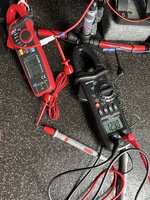
what i would do next is get a clamp meter reading with your shiny new "clamp meter" and "in the picture" get the voltage from a second meter showing the "pump motor" voltage while the pump is running


+++


like this:


1617206117321.png
 
a few pics of the ground connection/wiring will help too.
 
Ok.
1.9 Ohms is the pump -ve to an alternative ground. The pump ground returns back to the CBE unit and from there is grounded to chassis.
The battery voltage is 13.28v.
When the pump is running today’s draw is 5.63A and the battery voltage drops to12.4v

353746FF-4F49-4A24-8C1E-0CCD665CA9A1.jpeg
The wire length is ~2m for each run (2m for the positive and 2m for the negative).
The wire is sourced from 12v planet ;
"Single Core Thin Wall Cable - 2.0mm² 25A

If there’s an issue with these figures the other option is to run the pump negative to a point that’s only 10cm from the pump - but I’m not sure this will make any difference?

Thanks
Ollie.
 
The readings look ok...

Its good practice to keep cable runs as short as possible,

1.9 ohm on the ground is a bit high, id like to see 0.x ohms, so if you can ditch that long ground and connect to the other close ground. (Leave the existing in situe, just run a new wire).

Also fatter wire is always better, but the voltage reading is still ok when the pump is under load. So that implys the red feed cable is ok.

Not sure why the Amp draw is so far out from the 12v 10L pump spec...... they state 3.4A.?

Screenshot_20210402-091057_Chrome.jpg

Maybe a design change?

Though they do give you a 10A supply fuse.......

What does the A reading show when the pump is free flowing?.... ie all taps open to less back pressure for pump?

Then what does the amp draw show when the taps are closed and pump pressurises the line......untill the pressure switch cuts out the pump?

.
 
Fyi..

The pump secs.

12v @ 3.4A is 40.8W (w=v*a)

Your readings show,

12.4v @ 5.6A is 69.4w
 
i just watched this YT vid from Greg about a simple 12v pump setup.

worth a watch for some basic info.


.
 
@OllieGBR Have a look at the plumbing components, no components bore should not be smaller than the bore of the pump discharge port.
I suspect the pump has back pressure due to a restriction other than the NRV.
There are frictional losses in the whole system, the longer the system and the more bends, changes in diameter etc result in turbulence, with a camper water system this isn’t too critical but the system minimum bore is.
 
@DXX I followed yours and @Dellmassive advice. I simplified the plumbing by reducing the number of connections and 90 degree bends.
I move the earth to the local connection, wire length of 10cm verses the 2 meters.

I managed a trip the the Peak District over the weekend, worked from the van on Friday on a plethora of Zoom calls and it had a good test. Both hot and cold water now working well off the 5Amp fuse.
Diesel heater a real treat when retiring to the van in 0 Degrees too :)
Nespresso and milk frother with my mini barista made my friend and I very happy campers indeed!

Thanks again all for your help.

I just have the water pump panel to replace and c'est fini !!

Already booked another weekend in May.

Ollie
Good news, plumbing is like walking, best done in straight lines!
 
Back
Top