The shunt should be between the batteries and everything else before it gets to earth otherwise it can't see what's going in and out of the leisure batteries.
Last edited:
some observations:I think the problem is somewhere in this set up as the problems occur soon as the leisure batteries / DCDC charger are connected to the van via – firstly the cable that is already there under the drivers seat, and secondly when I only had a connection to the pos van batt (12v trigger wasn’t even connected)
WHY – that, is the question.
Ok here are some pics which are a bit shit so I thought I would sketch it out – which also isn’t very good
But here is explanation
I have cross connected 2 x 100Ah lithium batteries in parallel so the supply and feed go into POS on Leisure batt (LB) 1 and the earth is taken from LB2 through 100amp fuse both batt are connected ++ and Neg neg using 100A cable
(Taken from a diagram on net)
Feeds into DCDC charger (under drivers seat)
Feeds out of DC charger
- From starter battery to DCDC charger I have used 100A battery wire, at the battery end a 70amp fuse and the charger end a 50amp fuse
- 12v ign wire (from FB in drivers footwell)
- Solar pos input through 20amp fuse (solar neg is taken to earth point on van)
Feeds off LB1
- From the charger to LB1 56A cable fused with 50amp fuse
- Earth to Neg on LB1 56A cable
- Supply feed to fuses and switch panel in van 56A cable fused with 50A through an isolator switch.
- Plus and neg feed to 350w inverter
There is a shunt meter also fitted, main Neg is taken to van earth, 2nd Ned is to the Neg on LB1 and a small pos feed from LB1
View attachment 139863
View attachment 139864
View attachment 139865
View attachment 139866
View attachment 139867
View attachment 139868
View attachment 139869
View attachment 139870
View attachment 139871
View attachment 139872
View attachment 139873
View attachment 139875
Are you on a T6 or 6.1?
so you put the neg from DCDC to van earth point and not neg on leisure battery? as Dellmassive says - will it make any diff??


The 12v IGN trigger isnt needed for most DC-DC chargers as they will AUTO switch on when they detect 13.2v or above from the starter battery.(12v trigger wasn’t even connected)
WHY – that, is the question.
I've added that observation to the list above, well spotted.Your inverter negative is in the wrong place, it defeats the shunt as well or rather any use of the inverter would not be logged on the battery monitor.
Wouldn’t the DC-DC charger trigger the alternator regardless? Even if the starter battery was charged, the alternator wouldn’t shut down because the DC-DC would be pulling 30-40A. If the alternator did shut down, the starter battery voltage would soon drop enough to call the alternator due to the load from the DC-DC. That’s how I understand it, but I may be wrong.But it will demand a drain on the alternator where a smart alternator is fitted to keep charging the leisure batteries when the van decides it doesn't need it to charge it's starter battery
Yes, thats correct . . and what i saw during testing . .Wouldn’t the DC-DC charger trigger the alternator regardless? Even if the starter battery was charged, the alternator wouldn’t shut down because the DC-DC would be pulling 30-40A. If the alternator did shut down, the starter battery voltage would soon drop enough to call the alternator due to the load from the DC-DC. That’s how I understand it, but I may be wrong.


you should start you own thread @Epic-Rob . its a nice setup you have.thanks chaps.
i am in NZ and its near midnight now so i will study that tommorow and poss pull it out and start again

 kojaycat.co.uk
did think about it but am not very media friendlyyou should start you own thread @Epic-Rob . its a nice setup you have.
would be nice to keep it all in one place.
start your own build thread here:

then you can add your setup and mods going forwards . . . well help out on that thread too.
.
Cheers for the info. I used the ign feed when I fitted my Orion, I already had one available under the passenger seat & I didn’t trust the new fangled auto sensing. I’m a binary kinda guy & I wanted to be sure that if the engine was running, the battery was charging. None of that ambiguous maybe/maybe not nonsenseYes, thats correct . . and what i saw during testing . .
The starter battery rapidly drops in voltage causing the alternator to kick back in . . . but it will cycle on/off a lot.
without the IGN feed the DC_DC will switch off at say below 12.6v and then back on above 13.6v - causing the cycling effect.
its DC-DC charger specific on how and when they will turn on/off.
WITH the IGN feed the dc-dc will stay on to a much lower starter voltage, say 11.9v which reduces the cycling effect. . . .
without IGN feed average ( Traditional ALT) on/off : 13v - 16v
with IGN feed average (Smart ALT) on/off : 11v-16v
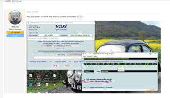
DC-DC on/off voltages listed here - [Guide] DC-DC Charger (for leisure battery) -- How I Done It --
View attachment 139895
.
AUTO VSR feature listed here - [Guide] DC-DC Charger (for leisure battery) -- How I Done It --
View attachment 139896
.


OK Q on cable size and fuses.some observations:
.
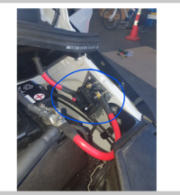
A- this looks fine, but I've had issues with this style of breaker switches getting hot causing volt drop when pulling current - so keep an eye on it . . . if it starts to get hot swap out for a MIDI or MEGA fuse.
View attachment 139887
.
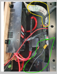
B- is this the main chassis ground connection in yellow? - of so the green? should be both the LB1 + LB2 NEG feeds.
View attachment 139886
both battery NEGS need to got to the SHUNT, then one common GROUND from the SHUNT to the van BODY. Also the gauge of the cable needs to be the same thickness as the main POS as it will be carrying the same high current . . . so if you use 150A cable for the POS, then you need 150A cable for the NEG . . .
if 2x 150A POS then you need 1x300A for the main NEG from the shunt ( same as you have done with the main starter battery feed)
..
C - where is the second battery? - each battery needs a fuse next to the POS interlink cable.
View attachment 139888
...
D - Fuse should be on the POS side of the battery. (technically it could go on the NEG side, but depending on the circuit layout the power could fin an alternate route to ground so POS is always best place)
View attachment 139889
.
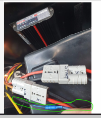
E - the second LB2 should have a direct connection to the shunt, it can go to either the LB1 or the shunt, whatever is shortest.
yellow or blue is ok, red is not right, the shunt will not read the power correctly.
View attachment 139890
F - where is this master switch in your schematic?
View attachment 139892
.
G - can you post a pic of your starter battery NEG terminal and connections
H - Inverter NEG connection needs to do direct to chassis ground, same as all you loads NEGS to chassis. . . ONLY the LB1 & LB2 NEGS to shunt - then shunt to chassis. credis to @Grim Reaper for spotting that one.
View attachment 139893
I - Fuse layout - this is where the fuses would normally be, as close to the battery POS connections as possible.
View attachment 139894
J -
