You are using an out of date browser. It may not display this or other websites correctly.
You should upgrade or use an alternative browser.
You should upgrade or use an alternative browser.
LED Interior Cargo Lights - How I Done It.
- Thread starter Dellmassive
- Start date
Amazing thanks. I think I saw those connections this weekend when wiring up tweeters into the dash.
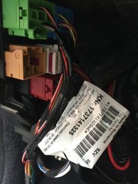
Any idea if there is wiring for the courtesy circuit near the rear - barn doors, off/side if possible?
That's where my control panel for the LED strips is - ideal place to add the mosfet and dimmer
Any idea if there is wiring for the courtesy circuit near the rear - barn doors, off/side if possible?
That's where my control panel for the LED strips is - ideal place to add the mosfet and dimmer
It doesn't run to the back doors. It branches off about half way down the van and across to the cargo light in the centre of the ceilingAmazing thanks. I think I saw those connections this weekend when wiring up tweeters into the dash.
Any idea if there is wiring for the courtesy circuit near the rear - barn doors, off/side if possible?
That's where my control panel for the LED strips is - ideal place to add the mosfet and dimmer
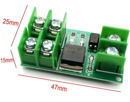
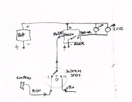
Hi, I’m attempting the MOSFET install this weekend, but the unit from eBay hasn’t arrived.Hi again Matty - sorry for the delay. Ye,s the wiring diagram is correct. The important thing is to make sure you buy a MOSFET module where the positive output and 12v supply positive are common and it's the negative side that is switched. The eBay hyperlink on the diagram will take you to one of the right type of MOSFET Switch. They generally have 'YYNMOS' written on the modules themselves. Good luck!
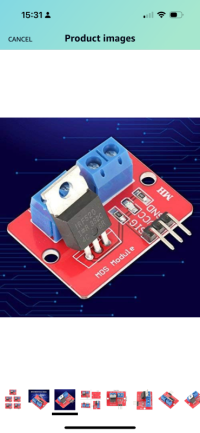
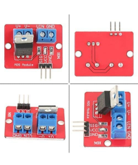
Would this one from Amazon suffice? I noticed it doesn’t seem to have an opto coupler
Bench Tested my mosfet as per @Mccoatup ‘s diagram. It works! Lovely seeing the LED strips dimming up and down.
The issue I have is that it appears all my lights terminating at the control panel appear to be switched positives, and they must share a common negative somewhere as there are no -ves from the lights at the panel - only a single common negative cable.
I was planning to have several of the lights linked together on a Mosfet located behind the control panel.
Help! How can I move ahead from here? I’m out of ideas!

Don't panic (yet!) I think all you need is a module with a different type of MOSFET (PMOS rather than NMOS), which cost you another £3.38. I will have a rummage around in my shed tomorrow and see if i have one. If not I will get one and confirm all is ok. I only focussed on the switched negative version as that was the way my van was wired.
Amazing, thanks! That would be so handy if it’s possible.
Didn’t know about Pmos and Nmos, but got some vague recollections of n type and p type transistors from my Saturdays working in Maplin as a student!
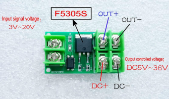
Now then, I also have 4 of these units from Amazon which have mosfet F5305S… is that Pmos?
Didn’t know about Pmos and Nmos, but got some vague recollections of n type and p type transistors from my Saturdays working in Maplin as a student!
Now then, I also have 4 of these units from Amazon which have mosfet F5305S… is that Pmos?
Hi @meza Yes those units from Amazon should be fine as they are opto-isolated and have a switched positive connection. I did dig out a similar module this morning, wired it up, tested it and all was fine. The particular unit I used didn't have screw terminals on the input side so I have ordered one pretty much identical to the ones you have, just to be 100% sure of what I am recommending. Won't be here till March 18th though. I've updated my diagram to cover both variants (switched positive and switched negative) now but won't post it till I've tested out the new one.
You also asked about the red coloured modules you posted about last week. They can't be used as the input side is not isolated by an optocoupler. It needs to be, as the negative side of the van courtesy light circuit doesn't go to van earth directly - it goes through a pulse width modulated switch to implement the dimming function.
You also asked about the red coloured modules you posted about last week. They can't be used as the input side is not isolated by an optocoupler. It needs to be, as the negative side of the van courtesy light circuit doesn't go to van earth directly - it goes through a pulse width modulated switch to implement the dimming function.
hi @Mccoatup thanks. I sketched this up and was going to give it a try - but realised I think I’d have to run an additional +ve wire round to the b pillar switch (as it’s running off a local ground currently as per your original diagram)
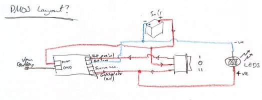
Having pondered things some more over lunch, I had another idea. See if you think this would work…
I stick with the original negative switching, and use it to control the common negative at the control panel. That way, the four light switches on the control panel are overrides - ON means that light is controlled by the b-pillar switch and mosfet. OFF means that light is disabled entirely.
Have I got that right?
there could be some side effects…
- The voltage display on the panel won’t be reliable any more?
- I ought not plug anything into the 12v socket, as the whole panel current draw is going through the mosfet board
- likewise for the control panel USB power socket
Another Q - am I right in thinking the current for the lights passes through the SPDT switch, so the cable for that need to be adequately sized.
Forget what I said about switching negative at control panel… I realised there is no negative for the lights there. Only negative for the other things like LED indicators on each switch, USB charger and ciggy socket.
I have however located the negative wire for the panel in the wiring cupboard with the battery.
I have however located the negative wire for the panel in the wiring cupboard with the battery.
I think you're best to stick with the switched positive version as you have sketched. Could be a number of unintended effects or unkowns otherwise as you say. This is the same as the diagram I have drawn other than I have a 2 way rather than a 3 way switch. Only an issue if you open the door in the middle of the night whilst people are sleeping in the back and you don't want the lights to come on.
I've attached my diagram now anyway.
I've attached my diagram now anyway.
Attachments
Agree with you on those side effects - not ideal.
I've found a unused 2.5mm2 cable running between the -ve return for all the lights and the control panel - so I can use this to send a common -ve for the lights up to the control panel - and use the original nmos board.
Next hurdle - realised I've run the cable (~5m) to the SPDT switch using small 0.19mm2 cable, and I've got around 50w of LEDs to put on them - and that's going to be a massive voltage drop and too much current for the cable.
To save me tearing that out and running larger (2.5mm2?) which will be a royal pain(!), can you think of a way to redo the circuit, and maybe add another mosfet to allow only switch level current to run to via the SPDT switch?
I was thinking about the possibility of the switch providing a choice of
0 - 0v
I - PWM
II - 12v
on a single return wire to the mosfet.
So avoiding any LED current traveling via the switch.
Any dice?
This has turned into quite a project!
Another solution:
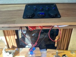
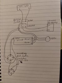
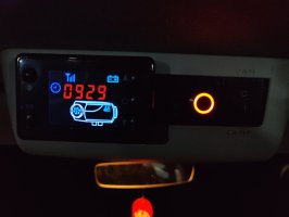
DPDT switch in cab overhead console to switch between "van" mode and "camper" mode. Can be accessed while driving or from the rear when parked up.
Van mode - wired directly to bulb in overhead cab light so operates depending on how you have the overhead cab light switch set; doors, off, on.
Camper mode - works independent of the van lighting.
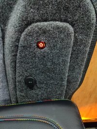
In both modes the led lights are controlled by momentary push button switches; on, off, dim(hold). I have 1 switch in cab overhead console which I can access while driving. 1 switch in b-pillar and 1 switch in c-pillar. The leds on the switches are on when the switch is active.
(The switches could be wired using a single wire and local earth, but you would lose the switch led)
The brains is an led dimmer (V1-F) from AliExpress.
Input 12v is from the DPDT(van or camper). Output 12v is to the led lights. The switch signal is from the momentary push button switches.
DPDT switch: 0.74ï¿¡ |Kcd2 6pin 21x15mm Dpdt Black White Push Button Rocker Switch On-off-on On-on Boat Power Rocker Switch 6a/250v 10a/125v - Switches - AliExpress
momentary push button switches: 0.4ï¿¡ 83% OFF|Mini Push Button Switch Waterproof | Waterproof Push Button Switch 12v - Electric - Aliexpress
V1-F: 8.53ï¿¡ 24% OFF|Dimmer Led Single Color | Dimmers Led Recessed Li | Fade Led Dimmer - 1ch 8a 12v-48vdc - Aliexpress
Sorry about the pic quality... And console panel is a temporary mockup until I get time to make the final version...


Interesting solution! So in van mode do the push buttons have any effect? Or do they only allow dimming if the cabin light is already on - eg door open or cabin light switch to ON.Another solution:
DPDT switch in cab overhead console to switch between "van" mode and "camper" mode. Can be accessed while driving or from the rear when parked up.
Van mode - wired directly to bulb in overhead cab light so operates depending on how you have the overhead cab light switch set; doors, off, on.
Camper mode - works independent of the van lighting.
In both modes the led lights are controlled by momentary push button switches; on, off, dim(hold). I have 1 switch in cab overhead console which I can access while driving. 1 switch in b-pillar and 1 switch in c-pillar. The leds on the switches are on when the switch is active.
(The switches could be wired using a single wire and local earth, but you would lose the switch led)
The brains is an led dimmer (V1-F) from AliExpress.
Input 12v is from the DPDT(van or camper). Output 12v is to the led lights. The switch signal is from the momentary push button switches.
DPDT switch: 0.74ï¿¡ |Kcd2 6pin 21x15mm Dpdt Black White Push Button Rocker Switch On-off-on On-on Boat Power Rocker Switch 6a/250v 10a/125v - Switches - AliExpress
momentary push button switches: 0.4ï¿¡ 83% OFF|Mini Push Button Switch Waterproof | Waterproof Push Button Switch 12v - Electric - Aliexpress
V1-F: 8.53ï¿¡ 24% OFF|Dimmer Led Single Color | Dimmers Led Recessed Li | Fade Led Dimmer - 1ch 8a 12v-48vdc - Aliexpress
Sorry about the pic quality... And console panel is a temporary mockup until I get time to make the final version...
View attachment 232130
View attachment 232134
View attachment 232135
Any chance you could do a quick demo video?
In van mode, switches are only operational when cab light is lit. Then the switch can turn on/off/dim the rear lights. The reason I have the switch led wired to be on when the switch is active is so that it's easier to know when the switch is active.Interesting solution! So in van mode do the push buttons have any effect? Or do they only allow dimming if the cabin light is already on - eg door open or cabin light switch to ON.
Any chance you could do a quick demo video?
If someone wants to use the rear lights while I'm driving or when cab light is off I switch to camper mode.
I like it. From the spec it looks like the dimmer remembers the last dim level on power on, And there’s rf remote support.
I’d wonder how many LEDs can be run off the van’s cab lights.
Got my setup working today dimming with the mosfet and a manual override switch. Need to wire in the wireless dimmer next.
I’d wonder how many LEDs can be run off the van’s cab lights.
Got my setup working today dimming with the mosfet and a manual override switch. Need to wire in the wireless dimmer next.
Similar threads
- Replies
- 1
- Views
- 471
- Replies
- 2
- Views
- 278
- Replies
- 0
- Views
- 1K
- Replies
- 10
- Views
- 718
- Replies
- 0
- Views
- 162

