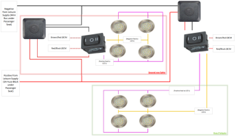
got some more ino and a few pics?Hi @Dellmassive this is what I've done so far but need to connect it all together to run both supplies
View attachment 130638
are both switches connected to the same LED light?
got some more ino and a few pics?Hi @Dellmassive this is what I've done so far but need to connect it all together to run both supplies
View attachment 130638
Sorry to get this post rolling again lolLED rear interior lights - How i done it.
so a few have asked, so i though i would just list it here as a post so i could refer back to it in the future.
The lights were purchased from The T6F shop over here >
View attachment 27565
We were planning to do the carpeting at around the same time, but for the purpose of this thread ill leave the carpeting bit out.
first thing to do was to remove the existing roof lining by popping out the grey plastic hex head pop studs, they all unscrewed easily, the center support bar popped out with a plastic trim tool... no problems so far....
View attachment 27566
The existing OEM LED light unclipped easily reveling the loom and connectors . . .
View attachment 27567
once the panels were out we layed them out on the floor and used a string line to work out where we wanted the new lights and what spacing we were going to have . . . . .
View attachment 27568
because we had already carpeted the panels, drilling into them was going to be a challenge ( the drill bit snagging the carpet) but and old car audio ICE trick was to put the drill in reverse and burn through the carpet, once burned through you could go through normally. . . . we drilled holes for the cable entry to the back of the panel and poked the wires through. . . . .
View attachment 27570
next up was to mount the lights, we used the small self tapping screws that comes with the kit to screw into the backing board, then fitted the covers over the screw fixings . . . .
View attachment 27571
next task was cable management, we cut off the small two pin connectors and layed out the cables to roughly where we needed them. We used white gaffer tape to tape down the cables to stop them ratteling etc . . . . we bought the excess cable through the OEM light fitting hole.....we decided to keep the OEM LED lights as dummy units, the also helped out as a good cable way and access panel of sorts to get to the connections . . . .
View attachment 27572
now the new LEDs were fitted we could refit the panels in the back of the van . . . we pulled the existing loom and original connectors out the hole where the old light was. . . . . .
using a multi-meter we measured the BCM 0v ground wire and the BCM timed 12v+ wire (when the rear door was open) and joined them with crimp terminals to the OEM loom . . . leaving the original connector on the end.
***************************************************************************************
Factory Non-LED 3 wire setup:
(brown) - earth point left a-pilar
(brown/red) - connection 1 main harness (BCM switched neg 0v)
(red/black) - positive connection 1 main harness (BCM timed +12v) ( 7.5A fuse 24 holder C)
****************************************************************************************
Factory LED 2 wire setup:
(brown/red) - connection 1 main harness (BCM switched neg)
(red/black) - positive connection 1 main harness (BCM timed +12v)( 7.5A fuse 19 holder C)
****************************************************************************************
BCM rear light TIMER :
credit: @JCElec
You can change the time by changing module 09 chanal 038. standard value is: 21 (10.5 minutes) en you can change it to 254 (127 minutes). it's multiplying whit 30 sec.
@mmi Excellent info. Thanks. Seems to match with my observations in thread Led Rear Interior Lights - How I Done It.
- channel 38 in my van has value of 121 - and indeed I had observed the lights (obviously the new setting came with factory LEDs in cargo space) stay on for 60 mins.
*****************************************
View attachment 27575
once all back in the van we tested it all making sure that the new LEDs didnt flicker and also went off when the van doors were closed/van locked etc.
FYI: This van had the factory OEM REAR LED pack option so already had the rear LED light modules with no-rocker switch. also the loom had only 2 wires. It also looks like you will get an extended ON time of around 60mins before the lights shut off.
If your van has the standard rear filament lights you would most likely have a rocker switch on the lamp unit and 3 wires in the loom. (0v ground perm, 0v BCM switched, BCM timed +12v perm) The BCM shut off time will be around the 10 - 20 mins mark.
for people looking to have a override switch for say a camper etc then a fused +12v feed wire would be used to feed the lights in addition to the BCM feed. A blocking diode may be needed on that feed wire.
If your switched override feed was coming from the AUX isolated battery feed in conjunction with the BCM feed (from the starter battery) i would defiantly fit a blocking diode to stop any back flow of current from the AUX and STARTer battery.
some people just totaly disregard the BCM +12v feed and just use the new +12v AUX feed, though a warning on this point is that if the lights were left on all night there is a chance of discharging the feed battery to a dangerously low level causing possible damage. . . . . . low voltage cut-out are available to prevent this from happening.
A relay can also be used to shunt the lights from BCM van control over to Leisure battery for extended light on times for camper-van setups and the like.
Hope that answers some questions I've had. =]
More info over here > Dellmassive`s -- "how I Done It" -- Thread
.
Tons of info on here alreadySorry to get this post rolling again lol
I would like to swap the original 3 way rocker filament light that came with the van to LED strip lights, but to be controlled by a small 3 way rocker switch I will fit onto pillar...
I dont mind the 10min timer for now.
Could anyone do a diagram / drawing to help?
Thanks

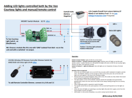
Just want to confirm the MOSFET solution worked perfectly! However the diagram shows the live to PMW and the Ve+ Being looped but I found the PMW had to be the vans original light circuit live (red & black cable) from the original 3 cable connector.It's probably buried in this thread somewhere, but here again is an alternative to a relay. Cost is not much more, and it will allow your extra lights to fade up and down as with the normal courtesy lights but without the chatter you get with a relay.


I have done this with two small dpdt switches from the courtesy light circuit which was super easy as the van was delivered with two factory fit courtesy lights.Would be easier to wire to 2 circuits or something. for lights on / off / on with door. Then split the lights into 2 sections rather than using individual touch lights... imagine having to touch 8 lens lights. In mine I have 2 spotlights roughly where the OEM lights are. Then an led strip all around the outside with on / off / on with door.
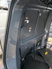
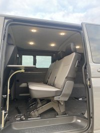
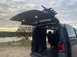

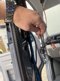
Of course I'll put a sketch together. it's mega straight forward though. (See post #104)@Samro, the flexibility of your setup looks superb, ingenious. I have too have a kombi and am after this kind of flexibility.
Can you operate the tailgate lights independently from the cargo area lights?
If you have the time would you mind posting a wiring diagram at some point?
Much appreciated. No rush, whenever you have time. If you're anything like me, it don't take much coaxing!Of course I'll put a sketch together. it's mega straight forward though. (See post #104)
Note that the photos were pre dimmer switches.
(The dimmers are fitted prior to the dpdt switch and only work on the leisure bank. When in "position 1" the lights just come on and off as per the factory setup and cannot be dimmed.)
If camping, the second row or rear/tailgate lights can be dimmed or isolated independently.
I'll put a sketch tomorrow when it's not Friday night and I've not been coaxed into drinking so much vino!
