Leisure Battery Charging

So, share the secret then because unless I am very much mistaken the DS300 has a 70 amp ignition controlled relay and is not a DC-DC charger??????? For self converters Reg 10 is of no interest so nothing gained there. Do you work for CBE or something?

Hi Travelvolt - definitely don't work for CBE - sorry to disappoint - we don't sell any components unlike some!! ;)

The DS300UK has a fet controlled link, if it was just a 70A ignition controlled relay what would happen when the relay was activated with say a 14.8V vehicle circuit and a depleted 11v aux battery - you'd have hundreds of amps trying to cross the relay so it cannot be just a straight 70A relay link as you suggest. It varies from a DC to DC in that it has no microprocessor controlled phased charging algorithm, the FET merely limits it to a 30A max charge rate.

The reason I mention reg 10 is I've seen a number of conversions - both self build and 'professional' converter - that have had issues with burnt out wiring and auxiliaries catching fire for two reasons:

1. Very few people do the maths on wire sections and when they do they calculate at 12v and leave no headroom for the 15V it may see from the vehicle side or say the 14.5v it'll see from a DC-DC charger
2. Most people think that 12v components in a 12v 'car' system cannot have a problem as the voltages match.

it's not the compliance with Reg 10 I'm promoting - more the fact that the auxiliary components are disconnected whilst the auxiliary circuits are subject to an external charging regime from the alternator or battery to battery charger. A lot of those who install components in campers, professional and selfbuild, don't realise that the 12v Ikea LED lights they've bought may be subjected to voltages that they are not rated or tested at during a charging regime as they were never desgned for automotive use.

With the auxiliaries being disconnected during drive charging by a system - CBE or otherwise, no matter what the method of charging - this over voltage is not an issue for the consumers that folk like to fit to their campers which are not reg 10 compliant and hence why I mentioned it.

Yes, the average self build will not know how to check whether a component meets UNECE Regulation 10 and will not validate the certificate and test report that accompanies it and for that reason Reg 10 is irrelevant - but the very reason that they struggle to understand why the need for the reg, is why they should adopt the principle. It'll also stop 'em struggling to understand why there's a burning plastic smell from the 12v Aldi fairy lights they installed in their roof as they trundle down the M6 at 70mph! :)
 
more the fact that the auxiliary components are disconnected whilst the auxiliary circuits are subject to an external charging regime from the alternator or battery to battery charger.
If I read this correctly you are suggesting that leisure circuits like fridge etc are disconnected whist any charging is underway? Unrealistic.
I chose to replace the VW Factory designed relay for a DC-DC charging system to avoid over voltage and properly charge the leisure battery systems.
 
I think he also is mistaken about wiring CSA and voltage. Higher voltage = lower current therefore cable size can be smaller. I remain unconvinced about the CBE DS300 being suitable for a vehicle equipped with IA.
I do sell components, you are right, but my only bias is towards quality and suitability.
 
Hi Pocc, I'm particularly interested in power systems and I'd be interested to hear how your batteries were connected for datalogging,
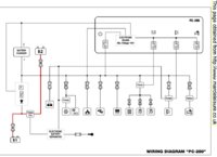
according to the DS300 schematic its a simple VSR, set to switch on at 13.3 and off at 12, though the manual has an obvious error here: :)

ds300_error.jpg


Maybe they've changed the design but the DS300 schematic I have shows no current limiting and no FETS, just the voltage detection
for the relay, which simply parallels the starter and leisure batteries, just the same as any split charge relay, with no visible means
of 'changing the charge voltage' or limiting the current. Maybe theres a more detailed schematic out there?
As well as at low voltage and 'alternator idle', does your system also disconnect (via the VSR) whenever the voltage is in its 'regenerative braking' (ie high voltage) phase? So you've changed the VSR from "off-below-12, on-above-13.3", to a windowed operation?
I'm assuming you have something like this if your logs dont show any regen-braking voltages? I'm genuinely interested in your findings.
Cheers
Phil
 
Last edited by a moderator:
Hi Loz, There are three output boards on the CBE kit, 1 for circuits that are permanently connected, 1 for circuits that are disconnected when the engine's running and one for the fridge which can be set via a jumper to either run all the time or only when the engine is running.

If you have a California, you'll have no problem as a type approved vehicle with any of your components as they have all passed reg 10 and will have an 'E' mark on them. The issue I was trying to highlight by mentioning 'reg 10' really is with conversions that hook up none automotive components (usually because they're cheap) to an automotive system.
 
If I read this correctly you are suggesting that leisure circuits like fridge etc are disconnected whist any charging is underway? Unrealistic.
I chose to replace the VW Factory designed relay for a DC-DC charging system to avoid over voltage and properly charge the leisure battery systems.
This is an interesting discussion, mine is set up by the converter so that when a run signal is detected all the auxiliary systems (except the fridge) are disconnected I wondered why and now I think I understand.
 
I think he also is mistaken about wiring CSA and voltage. Higher voltage = lower current therefore cable size can be smaller. I remain unconvinced about the CBE DS300 being suitable for a vehicle equipped with IA.
I do sell components, you are right, but my only bias is towards quality and suitability.

Oh travelvolts - you are so wrong about me being wrong that it really does worry me!! Physics lesson on the first electrical equation any of us learn - ohms law:

V=IR,
I=V/R

Therefore increase the voltage - increase the current.

In case you think you're still right - have a look here:

Ohm's law - Wikipedia

Phil, Yes I looked at the manual and install instructions and took them for gospel too - despite the anomalies, hence why I always fitted a more complex system. However when I did connect one as described and logged the voltages, there was a potential difference between the two connections much greater than could be causedd by any connection voltage drops. I suspect CBE do need to alter their paperwork though.
 
Hi Pocc, I'm particularly interested in power systems and I'd be interested to hear how your batteries were connected for datalogging,
according to the DS300 schematic its a simple VSR, set to switch on at 13.3 and off at 12, though the manual has an obvious error here: :)

View attachment 24140


Maybe they've changed the design but the DS300 schematic I have shows no current limiting and no FETS, just the voltage detection
for the relay, which simply parallels the starter and leisure batteries, just the same as any split charge relay, with no visible means
of 'changing the charge voltage'. Maybe theres a more detailed schematic out there?
As well as at low voltage and 'alternator idle', does your system also disconnect (via the VSR) whenever the voltage is in its 'regenerative braking' (ie high voltage) phase? So you've changed the VSR from "off-below-12, on-above-13.3", to a windowed operation?
I'm assuming you have something like this if your logs dont show any regen-braking voltages? I'm genuinely interested in your findings.
Cheers
Phil

Hi Phil screen dump of data logging attached on a 'drained' aux battery sitting at around 11v at commencement of run.

Vehicle battery voltages varied between 12.7 and 14.8v. Max voltage seen at aux battery was 14.24 - around what I'd want to see at a standard lead acid battery for charging. What else is apparent is that CBE system is charging in phases - hence the steps - and NOT just as a link VSR relay.

The drive was for around 40 minutes. Initially - as expected with discharged batteries - the stop start did not cut in (as it will have sensed low voltage on vehicle battery) but by around 11:49 it started to operate. when you zoom in to the data points you can actually see the engine stopping and starting again.

The vehicle was parked up at around 12:03 and every consumer in the camper turned on, diesel heater, lights, water pump and a 100w load plugged in to aux sockets. The blip at around 12:20 was me checking the logger voltages and accidentally knocking the clip off :oops: Before driving back to base between around 12:20 and 12:29.

Hope this satisfies your curiosty, if you want I can send you the CSV file on a PM.

T6 CBE DS300UK Aux Charge.jpg
 
Vehicle battery voltages varied between 12.7 and 14.8v
okay theres your regenerative braking...
Pocc said:
Max voltage seen at aux battery was 14.24
... but not seen at the aux battery, which is directly connected by the DS300 relay.
Just an observation, I would have thought .56v was quite a high loss for such a short cable run, even given typical charge currents.
Pocc said:
What else is apparent is that CBE system is charging in phases - hence the steps - and NOT just as a link VSR relay.
It looks just like a VSR switching in & out, but 'why' is what puzzles me. Did I understand correctly that you've modified the simple on/off switching points for the relay? All very intriguing! :)
Rather than starting the test with a low aux battery, a low starter battery would ensure strong regen braking was happening, to give the trace some emphasis.
Then if you could overlay the aux battery and starter battery traces, you'd see if the .56v loss was constant
afro.gif

Cheers
Phil
 
Last edited by a moderator:
You muppet pocc, for a given load if you double the voltage you halve the current is the point that I was making. The variation in charge level that you are logging is from the alternator control, not from the CBE unit. You may be clued up on data logging but I don't think you have much idea when it comes to vehicle electrics. D+ does not exist on an intelligent alternator and the CBE DS300 does not have any voltage or current control when it comes to the split charging aspect.
You need to run your test again with a longer run and an aux battery at around 90% full charge.

Sorry Travel volt - you are still wrong - you're basing your answer on p=I2R which is for a given POWER output,when the voltage increases, the current decreases. this is NOT how a consumer behaves which usually have a fixed resistance or impedence. To take your argument to it's logical conclusion 0 volts = infinite current, infinite volts = zero current.

If you don't believe in ohms law, try setting up say a consumer like an electric fire and hooking it up to a 1.5v battery - measure the current, then put 12v through it and measure the current.

I think muppetry here is on one side!!
 
Hi Phil,

Yes I don't know why either, the difference between the charge voltage in and output voltage to aux battery out was sometimes around 1v across 6mm2 wire about 300mm long in total, so no real resistance effects here to consider.

Also if it was just a straight VSR, why does it follow the step algorithm, which despite what travelvolt says is nothing like the alternator output or vehicle battery voltages. And yes travelvolt if you look at the statement the aux battery was discharged and so was the vehicle battery. Test was also completed later with a fully charged vehicle battery and discharged aux battery with no massive currents flowing to/from the aux.

I suspect there is more to the CBE link than they say it being just a VSR link. Their diagram includes an 'electronic battery separator' which in the flow diagram seems superfluous so I suspect this is a voltage regulator.

I didn't mention using the CBE system as a dig at anyone although it seems to have been interpreted as this, only to say that the CBE system can charge an aux battery.

We have around 30 T6's out there with them including 4 hire vans regularly driven by noobs and have only ever had one battery discharged beyond use - and the owner of that van admitted he'd left the fridge on from Feb to May this year. Our customers continue to recommend us as do the VW dealers who have dealt with us. So I really don't care whether someone thinks I'm related to kermit the frog for knowing that increasing voltage through a given circuit increases current
 
I think a better analogy to explain the voltage/current use on resistive loads, goes like this;
you have a 21W12v lamp the resistance is a fixed 6.8 ohms so at 12V it is 21W but if you increase the voltage the light gets brighter so the wattage increases and with it the current required.
and if you put this in a calculator.
upload_2018-6-18_16-55-28.png
upload_2018-6-18_17-5-8.png
 
Last edited:
We can use any CBE system with the DS300 controller which does modify the charge voltage as the FETs are using this to limit the charge current to a max of 20A.
Ah I see what you are saying now, you think the .56v loss across the VSR and its cables is somehow electronically controlled within the DS300?
But the only electronics in a DS300 is voltage sense to operate the VSR at 13.3v and release it at 12v, (its usual for a VSR to have some hysteresis) - this is what they call an 'electronic battery separator' :D - and for other voltage switched stuff (10v battery saver etc). The only item that actually links the two batteries and carries charge current, is the relay contacts.
The internal photos and the schematic seem to confirm this :) Whereabouts in the schematic are you seeing FETs limiting the current to 20A? This would entail PWM drivers controlled by the aux battery voltage, as that level of current cant be done using linears - the power dissipation would be huge.

The secret is finding the right connection (not D+ or engine running) that stops the DS300 'unlinking' when the alternator idles on coasting or when the vehicle battery is sensed as having sufficient charge.
...but isnt this is exactly what your graph shows, the relay cycling in & out... ?

;)

The ideal test would be a fairly low starter battery and a full aux battery. When the aux battery is full it wont take any current so the terminal voltage will climb, this is when you would be more likely to see nasty regen-braking voltages on the aux battery
afro.gif

I think that by testing with the aux battery discharged, you're ensuring that it draws a heavy charge current, which over your resistive cable/vsr combination is dropping over half a volt, so you dont see the high regen voltages.

ds200pc200.jpg
 
Last edited by a moderator:
Hi Loz, Yes your analogy is much better and much easier to 'test' than mine. I'm not that sure where I'd find an old lekkie fire nowadays to prove my point :(

daveyB - agreed on name calling, we all have much better things to do than get involved in tit for that responses.

Phil, the relay never dropped out during test except when the ignition was switched off. The reason I tested with a discharged aux battery was to allow high current flows between the batteries if the system would allow, as you'd expect to see with a VSR. It didn't exceed the 30a stated in the CBE manual as the split charge limit. It was this statement that prompted me to investigate whether there was voltage regulation or PWM in action. If it was just a VSR then the controller could not limit current by opening and closing relay points. A simple VSR switching in and out does not limit current, and therefore 'linking' a fully charged battery to a discharged one would have a massive current flow - which was not the case - current never exceeded 30A - attested by this being the size of fuse I used in the test circuit. Whats more is the voltages were not in phase (even allowing for voltage drops) at any time with the vehicle battery until the aux was charged up. At some point when I have a duff one arrive, I'll pull it apart and see what's regulating the flow to the aux. For now why it works remains a mystery, but it does :)
 
okay theres your regenerative braking...
... but not seen at the aux battery, which is directly connected by the DS300 relay.
Just an observation, I would have thought .56v was quite a high loss for such a short cable run, even given typical charge currents.

It looks just like a VSR switching in & out, but 'why' is what puzzles me. Did I understand correctly that you've modified the simple on/off switching points for the relay? All very intriguing! :)
Rather than starting the test with a low aux battery, a low starter battery would ensure strong regen braking was happening, to give the trace some emphasis.
Then if you could overlay the aux battery and starter battery traces, you'd see if the .56v loss
okay theres your regenerative braking...
... but not seen at the aux battery, which is directly connected by the DS300 relay.
Just an observation, I would have thought .56v was quite a high loss for such a short cable run, even given typical charge currents.

It looks just like a VSR switching in & out, but 'why' is what puzzles me. Did I understand correctly that you've modified the simple on/off switching points for the relay? All very intriguing! :)
Rather than starting the test with a low aux battery, a low starter battery would ensure strong regen braking was happening, to give the trace some emphasis.
Then if you could overlay the aux battery and starter battery traces, you'd see if the .56v loss was constant
afro.gif

Cheers
Phil
It isn't a VSR Phil, it's just an ignition switched relay.
 
Sorry Travel volt - you are still wrong - you're basing your answer on p=I2R which is for a given POWER output,when the voltage increases, the current decreases. this is NOT how a consumer behaves which usually have a fixed resistance or impedence. To take your argument to it's logical conclusion 0 volts = infinite current, infinite volts = zero current.

If you don't believe in ohms law, try setting up say a consumer like an electric fire and hooking it up to a 1.5v battery - measure the current, then put 12v through it and measure the current.

I think muppetry here is on one side!!
That isn't what we were discussing. The initial comment was about the sizing of conductors was it not? Or, maybe I misread your original thread (pitfall of trying to read long threads on mobile devices)
 
It isn't a VSR Phil, it's just an ignition switched relay.
The manual does say that its voltage switched Martin - although there is a misprint - 'on' at 13.3v and 'off' at 12v:
ds300_error.jpg
Its disabled when the ignition is off, but when the ignition is on, then according to the document its a VSR, switching on & off according to the input voltage
afro.gif


With Pocc's reference to 'their' system I initially thought they'd modified the switching circuit so it was off below 12v, on from 13.3v to say 14.5v then off again if the input voltage went above 14.5v (ie during regen braking) which is perfectly feasible. But apparently its all standard.

Pocc said:
For now why it works remains a mystery
Nah, there are no mysteries in electronics... :)
Pocc said:
but it does...
it cant work optimally, you cant properly charge one battery by simply paralleling it with another thats on average 20% discharged!

Right, 8pm, back to work for me... lots of doggies need a last wee then tucking into their beds, read em a bedtime story, lights out... :) (we're a boarding kennels!)
Cheers
Phil
 
Last edited by a moderator:
I think you hit the nail on the head Phil. You can't charge one battery to 100% and another to 80% from the same source without introducing some form of buck boost or PWM to the target battery. The relay in the CBE cannot be classed as a VSR as it cannot operate without an ignition signal. Not sure what the point of the electronic battery seperator is but I doubt it was intended to work with intelligent alternators. I will study the diagrams and data logging when I can view on a full screen but i suspect that the test conditions were manipulated to produce the desired result.
 
Back
Top