Retrofit: Power fold mirror with fold on remote lock

This is unusual to me but maybe your module has some additional functionality?

Generally speaking your mirrors should unfold when you unlock the van (your unlocking signal is connected). And then they should fold in when you lock the van.

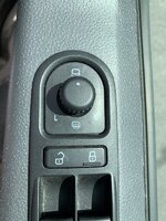
Is your mirror manual folding switch functioning correctly?
Are you sure that you haven't mixed unlocking signal with locking?

The mirrors open when opening the van, as soon as I turn the engine off and pull the key they close? This is with the switch in the L position? There is a jumper position on my module so maybe I’ll try this to see what other function it gives. With the switch in the mirror fold position the mirrors open when opening the van and close when locking. Do you keep your switch in this position?
 
Mine lock and unlock / open and close from outside the van ok. But the mirrors close when turning the ignition off. My switch is different to that one tho?
 
Think it could be the switch not having a 0 position, with the switch left on the wing mirror close position it opens and closes from the key fob no problem, with it left in the L position it auto closes the wing mirror when loosing the ignition signal. C7E1A905-B0C8-4F7F-BA23-E34DB0CCF77C.jpeg
 
Think it could be the switch not having a 0 position, with the switch left on the wing mirror close position it opens and closes from the key fob no problem, with it left in the L position it auto closes the wing mirror when loosing the ignition signal.
c7e1a905-b0c8-4f7f-ba23-e34db0ccf77c-jpeg.71685
 
You have T5 and mine is T6. Switches are different but both have exactly the same functionality.
Lack of "0" position on yours makes no difference.
I suspect that you didn't connect your wiring correctly.
 
  • Like
Reactions: mmi
green blue.JPG

yellow wire.JPG

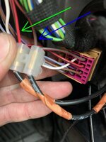
Can you see 3 arrows above(red, green & blue)?
Can you describe the function of each wire that these arrows are pointing at?
 
  • Like
Reactions: mmi
Yep, green and blue arrows are the open and close of the mirrors motors, red is from pin 8 of the door switch to close the mirrors.
 
If the red arrow is pointing at the wire going from the switch to the door control module then this wire needs to be disconnected completely.
And if your "green arrow wire" and "blue arrow wire" are also connected to the door control module then you need to disconnect them permanently as well.
 
  • Like
Reactions: mmi
If the red arrow is pointing at the wire going from the switch to the door control module then this wire needs to be disconnected completely.
And if your "green arrow wire" and "blue arrow wire" are also connected to the door control module then you need to disconnect them permanently as well.
Ok cheers mate, I’ll pull the door cards off and disconnect them.
 
Does anyone have any idea what has happened to the Amarok mirrors with indicator? I would like one but they seem to have disappeared from the market..
 
If the red arrow is pointing at the wire going from the switch to the door control module then this wire needs to be disconnected completely.
And if your "green arrow wire" and "blue arrow wire" are also connected to the door control module then you need to disconnect them permanently as well.

Hi rob,

only just got round to pulling the door card off and slightly confused again now,

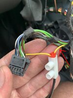
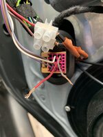
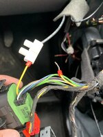
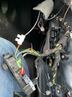
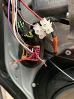
I have disconnected the feed from the switch (yellow) and connected my cable from the relay to this? The other side of the cable will be taped?

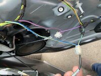
the blue yellow and purple cables have been cut into and also feed back to the relay for the lock and unlock signals? I haven’t touched these from previous.

The supply from the Original motor Control has been disconnected red Brown, brown red, my cable from the relay has been wired in for opening and closing the mirrors? I’ve left the original open and close feeds off from the multi pin plug? Do I also need to do this on the passenger door? I’m guessing so all the control conked from the new relay and not the original feed from the multi pin plug?

I haven’t removed the passenger door card to remove those feeds yet but with the mentioned cables discounted the mirrors don’t move no matter what state the switch is in, I can here the relays clicking but no movement or on lock or unlock. With them connected the mirrors opened and closed off toggling the switch state.
Kind regards,

ashley.

B9D760CF-038F-47C4-B178-32ABD99DDB47.jpeg

C7B31769-8656-48A1-B991-1091BBAE9143.jpeg

6EB770F3-C756-44C5-A950-3CED75A29799.jpeg

B0115631-9E9D-484F-ADE9-9D4F214D22BF.jpeg

DCBEDEEF-317D-4C79-902C-17815D98B106.jpeg
 
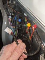
Basically both, red warning light and projector, are connected together as follows
+12V from red/white main supply going to door control module
0V from door lock mechanism (black on RHS, black/brown on LHS), these wires bring 0V only when corresponding door is open.
Please see below
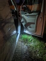
@Robert thanks to this thread I wired up some door courtesy lighting today but I noticed that when the door is closed the Black wire does not revert to 12V but about 5.5V, meaning that my courtesy light is gently on whenever the door is closed. I can't actually see it when closed, but that red / white line is permanently live, so I guess I now have a small drain on the battery?
PXL_20201122_170323950.MP.jpg
PXL_20201122_165021922.jpg
 
@Robert thanks to this thread I wired up some door courtesy lighting today but I noticed that when the door is closed the Black wire does not revert to 12V but about 5.5V, meaning that my courtesy light is gently on whenever the door is closed. I can't actually see it when closed, but that red / white line is permanently live, so I guess I now have a small drain on the battery?
View attachment 92790
View attachment 92791
There is nothing to worry about mate.
My wiring method is 100% safe and there is no unexpected drainage from the battery.
If you can't see your new lights when the door is closed try to pretend that they are closed.
Simply use screw driver and click in fully your door locking mechanism latch. You should see all internal lights going off plus your newly installed in the door.

EDIT:
Some inexpensive volt meters give very funny(incorrect) readings.
 
Last edited:
  • Like
Reactions: mmi
There is nothing to worry about mate.
My wiring method is 100% safe and there is no unexpected drainage from the battery.
If you can't see your new lights when the door is closed try to pretend that they are closed.
Simply use screw driver and click in fully your door locking mechanism latch. You should see all internal lights going off plus your newly installed in the door.

EDIT:
Some inexpensive volt meters give very funny(incorrect) readings.
The led's glow faintly when I tested it off the door card with the window open. So the voltage is real. Will get a pic when I do the other door.
 
... I noticed that when the door is closed the Black wire does not revert to 12V but about 5.5V...
This is a little bit incorrect interpretation.
When the door is open Black wire supplies 0V DC (-ve)/GND and when the door is closed this wire "becomes effectively " volt free( like not connected to anything).

So to be clear my idea is about supplying permanent +12V DC(via local fuse) to one side of the light and then switched 0V DC from door locking mechanism to the other side.
 
Last edited:
  • Like
Reactions: mmi
This is a little bit incorrect interpretation.
When the door is open Black wire supplies 0V DC (-ve)/GND and when the door is closed this wire "becomes effectively " volt free( like not connected to anything).

So to be clear my idea is about supplying permanent +12V DC(via local fuse) to one side of the light and then switched 0V DC from door locking mechanism to the other side.
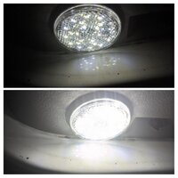
20201123_182907-COLLAGE.jpg
Used your trick with a screwdriver - closed top, open bottom.
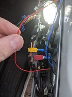
Here's my taps, when I was testing them with the light. And the multimeter was on these taps too.
PXL_20201122_154635496.jpg
(Ignore the red wire I'm holding)
 
Back
Top