Swapping my leisure battery to LiFePO4

If you're doing this, you may as well add a mega fuse holder and a main isolator switch between the busbar and battery.
Small counter opinion on isolator switches - they do take up space and add additional connections and switch interfaces that can cause issues. More so on higher current installs than @wallport one to be fair.

A well mounted main fuse that's accessible still gives the ability to isolate with much more simplicity.
 
Thanks guys - feeling better about this all the time. Will likely order the battery tomorrow, just waiting on a reply from another supplier who might have had stock (forlorn hope I suspect).

On isolator switches, from all this experience with the other battery I would be tempted but its just one more thing to complicate the install so maybe not. Making an isolator fuse accessible could be an issue - would really want it accessible outside the box as its a faff removing the lid every time (and the lid screws will have a limited number of cycles before they won't grip anymore). There is more space on the negative side than the positive which I guess is the wrong way around.
Yeah tbh a single main fuse is fine, it needs to be on the positive side though, and as close to the battery as possible.


One thing to consider, the fogstar terminals are the opposite way round to your battery:
1000007645.png

So you'll likely need to extend your current cables anyway, but makes placing the fuse easier with more room.
 
One thing to consider, the fogstar terminals are the opposite way round to your battery:
Oh no! Never considered that. How annoying.

So I guess the terminals will have to be away from the wall, busbar on both plus and minus and some thick cables traversing the width (or around the sides) of the battery to the terminals? Does that make sense?

Doesn't solve the fuse issue though.
 
What I would do, is firstly mount the 2x busbars for all the positive and negative feeds on the inside on the panel, so before they poke out into the battery box. Mount them inside of the 2 holes where the cables currently come out, maybe above each other (highly dependent on how much slack there is).

Then, put the battery in with the terminals closest to the rear (same orientation as your current battery but swapped) so positive on the right and negative on the left, this will mean your terminals will be at opposite ends. Then, run the single positive cable to a megafuse holder mounted on the wall next to the other midi fuse that's already there, then from that run another positive cable into the hole at the back of the battery box and to the positive busbar.

Run the negative from the left side terminal through the hole and to the busbar.

With the busbars mounted where you can get them, you can then run the main positive and negative cables to them, and it doesn't really matter where the battery terminals are.

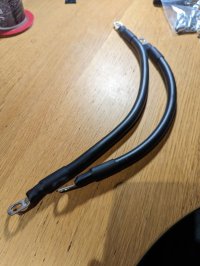
If you get decent battery cable it's really flexible, this cable is 240a 35mm² stuff.

1000007646.jpg
1000007041.jpg
 
Last edited:
I will be honest and say that this doesn't fill me with joy but perhaps I haven't got over the disappointment of the extra complexity yet.

I don't know about the plus side as I've never removed them but the cables on the negative side (or at lease the shortest of them as they were all pulled off as one) probably had 6 inches of slack max. Also that is without having to go round corners as the cables dont have good bend radius. I think the bus bar would have to be mounted very close to the existing hole. If we assume the same on the plus side then we end up with two bus bars somewhat adjacent (I know the new battery is shorter) to the opposite terminals.

Now that existing midi fuse is so inaccessible that I only got it out by unscrewing it from the panel first. So mounting another one there will have the same issue.

Thanks for those pictures as this does show that I don't need to worry about the bend radius of those.

I do hate sounding negative about the advice and I'm still pondering things but please can you explain what's wrong with my proposed solution above? I know I haven't solved the fuse issue either.
 
All depends where you can mount the busbars, one you've worked that out you can basically put the battery in whichever way you want to.

Essentially, work out where the existing cable ends that are on the battery at the moment will reach, mount the busbars in a good location based on this, and then route the new cables from the battery to wherever the busbars are mounted.

Above the battery box, next to the other fuses might be best for the Megafuse if the right side isn't very accessible.
 
What I would do, is firstly mount the 2x busbars for all the positive and negative feeds on the inside on the panel, so before they poke out into the battery box. Mount them inside of the 2 holes where the cables currently come out
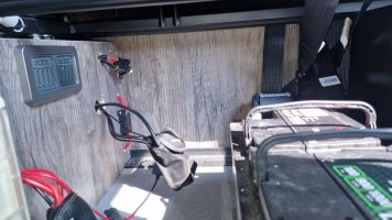
I would just like to clarify this as I'm a little confused (although I may be misunderstanding). The holes the cables emerge through is in the 'permanent' side panel so there is no access to the other side of those holes without ripping out the paneling. When the battery box (actually just a side and a lid - no ends and the other side is the panel the cables emerge though) is in place, the cables are emerging inside it adjacent to the battery terminals.
So the busbars will have to be screwed to the outside of the fixed panel near the holes and the cables will still emerge through the holes and then connect to the busbar. I am a little concerned about the corners these cables will have to go around as obviously they can't be the same orientation as the battery terminals.

Also, the existing battery sits against the fixed side panel providing some stability so that screwing it to the floor on one side only worked. The new one, however, presumably can't sit against the permanent 'wall' panel as it's height will cover at least one of the holes the cables emerge through.

Appreciate it if we could just clear up anything I'm misunderstanding.

Ahh, I assumed you could get behind that panel.


You'll need to work out where you can mount the busbars on the front of that panel then - the fogstar is narrower than your current battery so they could go below the holes in the panel where they come out from.
 
Right, we have a common understanding - thanks.

I really want to pull the battery out and suss it all out but the wife is camping with no hookup next weekend and hoping the existing battery will at least power the lights. Don't really want to pull it out and put it back... May have to order the battery and suss exact fitting afterwards.

The busbar example above had a plastic casing around it but I guess that's not necessary if it's inside the battery box. The volt planet site @roadtripper posted has various options - how many amps does it need to be rated at - oh and what fuse?

What I may do eventually is install stuff and temporarily cable to the existing battery but will have to be sure exactly how the new battery will sit.
 
The bus bar will likely be rated well above what it'll ever see, they're normally 200a or more. Just make sure it has the right size studs so your current ring terminals will go straight on.

As for the main fuse, go for a megafuse holder:

And then your fuse size should be based on what size your main battery cable is. For example 25mm² is rated at 170a, so your fuse would be below this - so 150a:

If you're ever thinking of adding an inverter (100pw would be fine with 105Ah LiFePO4) then size according to that. A 1000w inverter can pull 100a or so.

Obviously your negative battery cable should match the positive one as all your negatives go back to your battery.
 
With bus bars I'd always prefer a cover if viable as batteries tend to be in awkward places and it's far too easy to drop a spanner or screwdriver into the area.

I'd get some cereal boxes or cardboard packing and mock yourself up a box the size of the battery you want to fit. Doesn't have to be hyper accurate but I always find having a physical 3D shape makes it much easier to figure out how things fit together rather than just taking measurements.

And if your worried then consider this; you're not really changing anything you're mostly just extending the wiring. If at any point you're not happy you still have the option of fitting a decent lead acid leisure battery and coming back to it in the next couple of seasons. Even if you've got the Fogstar by then they are a popular option and you could move it on in the forum quite easily.

And for a confidence boost @NicolasH was kind enough to post an update on a very similar change they did:

 
Last edited:
20240507_120110.jpg
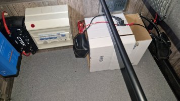
Bit the bullet and pulled the battery out. So here it is with my cardboard mock up in place. Various observations:
  1. I think the battery compartment is toast as fogstar confirmed that I need to allow another 12mm of height for when the bolts for the terminals are in place. The wooden lid won't therefore fit under the fuse banks.
  2. The screws into the floor that were holding the old battery on one side were just 25mm x 3mm self tapping screws. Very questionable if they are any use and as per a previous comment a contributer made, I'm certainly not drilling into the floor. Securing the new battery remains an issue.
  3. As the photo shows, the new battery can be made to fit between the holes that the wires emerge through. Unless it's seriously bad practice, I'm wanting to locate it against the side panel as per the previous battery as it will be easier to secure it. I would locate the bus bars above the holes and have covers on them as suggested - the tails are certainly long enough for this. If there is not going to be a box then I guess it's just covers on the terminals. Maybe there is something else to help insulate them as they will be on the outside next to where we store the awning now?
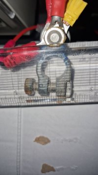
  4. I'm pretty sure the terminals are m8 maybe this photo confirms20240507_123339.jpg
Is there anything else I should do before putting the battery back?
More photos:
20240507_111019.jpg

20240507_105213.jpg
 
One thing to check if you are going lithium is you need to find where the battery setting wire from the CTEK is as that will need changing to change the charge profile.

Make sure you can find that while you have good access.
 
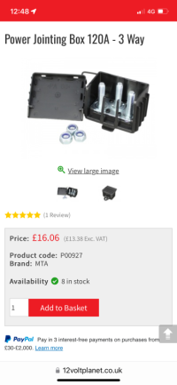
Rather than modifying the woodwork around the battery you could always use a plastic battery box fixed to the floor (and/or rear wall) with 2 x nylon straps screwed to the floor (one across, one along the box). This would not only isolate the battery connections and give protection for the battery from items stowed in the area, but also give a degree of flexibility for positioning and make the battery easily movable if you need to get to the fuses. You could surface mount the busbars (or junction box - see pic below) near the holes to attach the existing cables and then have suitable length leads to the battery tucked away in the battery box but with enough length to allow you to move it. The box is then secured tight up to the busbar covers. Hope that makes sense.

I don’t remember you mentioning an inverter so you won’t be maxing out the amps. The Fogstar is max 100amps (BMS limit) so you don’t need to go huge on busbars, cables and fuses. 150amp busbars will be fine, 16mm2 ready made battery leads are more flexible and cheaper and a 100a midi fuse is much smaller and easier to accommodate, (maybe in the battery box) than a mega fuse. If you do fit an inverter at a later date you can easily upgrade these elements.

So in sum:

- Battery in box strapped to floor.
- 200mm 16mm2 battery lead to 100a midi fuse (stowed in battery box).
- 16mm2 battery lead from midi fuse to new junction box attached near hole.
- single 16mm2 negative cable from battery to negative junction box.

So bits of buy:

Battery box:

IMG_6970.png
Straps to hold box down:

IMG_6971.png

Battery leads (make sure you specify the correct size connection at each end):

IMG_6974.png

MIDI fuse holder:

IMG_6973.png

Junction box (2 way also available) or a busbar with cover:

IMG_6972.png
 
One thing to check if you are going lithium is you need to find where the battery setting wire from the CTEK is as that will need changing to change the charge profile.
Ouch.
20240507_143012.jpg
So there it is going behind the panel presumably currently moulded together with the red wire which must go off to the smart alternator via a crimp connector or something. The manual says both wires are all of 20cm long! The positive battery terminal is currently at least 30cm away.
 
16mm or 20mm through crimp on the fat cables and Wagos on the thin ones especially if you can shove them back through the holes in the board too hide the mess... yes tape up those butt slices:thumbsup:
Get your Dymo labeller going and label the living shizzle out of the various conductors plus and minus, by now you should have a fag packet type wiring diagram idea of your system too and an idea of what's wrong if or when a component fails like my Renogy DCC50S did last weekend.
 
How do I separate the thin black cable from the thin red cable without access to the other end which is behind the panel?

Thanks @roadtripper for pointing out the issue which I completely missed. I'm going to have to put things back together this afternoon so if anyone has any thoughts, do please let me know.
 
So looking at the manual
1000007702.png
The black wire on the red and black wire needs to swapped from a ground connection where it is currently, to a positive 12v connection?

Is it possible that it's the thing black wire with blue connector that's already on your battery negative terminal? If not, then it's probably going off somewhere to a chassis ground. You'll need to trace that wire too find where it goes to. It's only 20cm long so it can't be going far!!n

Or, you could pull out enough of the wire to separate it and then add on an extra length to connect it to the battery 12v positive.
 
Back
Top