Victron (#TeamBlue) Advanced Systems + VRM - How We Done It -

Raul a/3

Member
T6 Pro

Victron (#TeamBlue) Advanced Systems + VRM - How We Done It -​


new thread started from - Seat Base Electric + EHU + Solar Install + Charger + DC-DC -- How We Done it --

previous content - Dellmassive’s "How I Done It" blogs.

additional content - Solar Sheds & Other Non-t6 Solar Projects - How We Done It -

starting off with @Raul a/3 Crafter install below.#


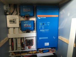
Managed to get some updated photos, and some are old photos as it was. Without further ado, here is our set up containing most important bits, that serves us brilliant.
6AB6F245-DC58-4833-9293-00E1D038304F.jpeg
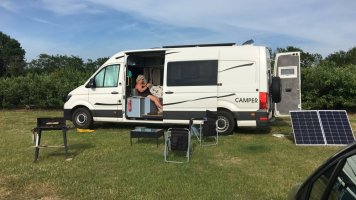
This is how we use our portable panels deployed when stationary.

4760A7C3-3693-47DD-B341-F2A9C1244CDA.jpeg
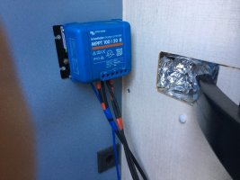
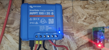
This charger caters for the portable panels, it’s right at the back, with solar cables at the back of the door. 571236BF-07E8-4909-A9BC-868B2B46BDAA.jpeg

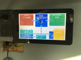
The touch screen 7” display , connected to the RPi. The hole next to it was a digital GX removed, it will be filled up with a bank of usb. 971270B1-4C61-4B28-B6D4-57EC3E74F8D8.jpeg
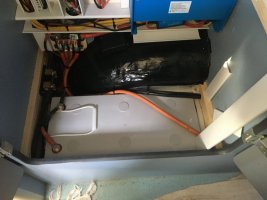
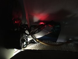
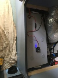
First ultramax 200ah lifepo4, with a ve bus temp sensor on neg post. This sensor is connected to the multiplus above, to control ehu low temp charging, also I can see on VRM what’s the temp in the van. 7B4973482-83DD-45C0-8143-3BFDC6E78E53.jpeg
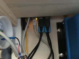
Here I removed some of the trunking covers for photo purposes only. The multi is connected to the RPi via mk3 ve bus-usb interface. The main solar charger, is networked with the second charger, and another temp sensor, to control low temp solar charging. 6785D065-BED0-4B91-A49B-DEA2379713F0.jpeg
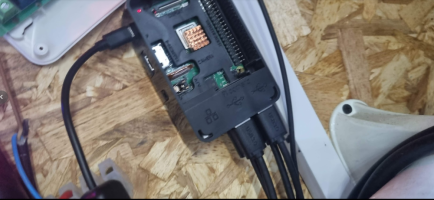
Bottom of RPi, with all ports used up. Anymore, and I will need a usb splitter.
 
Last edited by a moderator:
Next
14CDF9DF-5C4B-40C1-A071-C5B08A83C8C4.jpeg
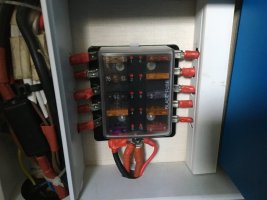
Low power 10 way distribution, fed by a 30a midi from high power distribution.
7C1C5025-F26E-455C-8D44-67346B6DA756.jpeg
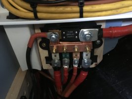
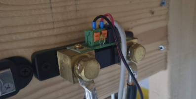
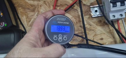
High power distribution buss bar, that connects the two batteries, mppt chargers, B2B and inverter. I chose to fuse each battery to a buss, with equal 35mm cable each, and 75mm for the inverter. Next to the left is the bmv700,
Notice, I have beefed the original anaemic bar, with two 15x3mm cooper bar, and bras bolts.
AD0207B7-0379-4542-94C9-B9680AD377BA.jpeg
Poor photo, sorry. Top of the RPi with ribbon coming from the display. Also, it has lan to the router.
7FD166C9-4941-4F4A-A971-9B579CC501A4.jpeg
Second 200ah battery, with the bt battery sense glued on top.

To be continued. Do not post.
 
Next
4A59523E-285C-49D2-A2DE-0A9CE02014D0.jpeg
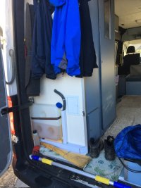
This is where I keep the portable panels when not used 2x 115 victron panels hinged with door butt hinges bolted to the frame
D0E786E4-4BED-4DC9-BD78-EE581342F917.jpeg
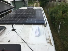
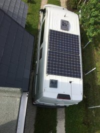
Roof panels mounted with renusol metasol plates and clamps, bolted through the roof, with plate inside. The panels are 88cell panasonic hibrid HIT 300w each. The cells are 5 layer cell silica, amorphous, that works brilliant in overcast, also very low temp coefficient in hot weather; very little derating. Also at the front is a max fan, a mimo LTE antenna at the back right, and turbo vent to the left above the shower.
40B4EC12-FA5A-46EC-93B0-4887640FF714.jpeg
Here is a better view, before I fitted the LTE antenna
7B80C51F-CDAC-4535-9C62-71E504AF9243.jpeg
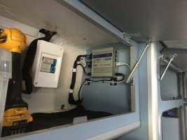
Top cupboard, with the solar fuses, and the teltonica router.

That’s it for now, happy to answer any questions, or receive any critique I may learn something new.
 
Forgot to add spare wheel carrier on the back door hinges and door itself. I had to relocate it, as the space underneath was taken by the underslung gas tank. 98342D82-CB99-4407-97ED-9F76D102D30E.jpeg
 
Very nice @Raul a/3 ....

Loving the 74A charge from EHU,,...the team blue force is stong.

So where's the T6? :mexican wave:
 
First ultramax 200ah lifepo4, with a ve bus temp sensor on neg post. This sensor is connected to the multiplus above, to control ehu low temp charging, also I can see on VRM what’s the temp in the van.

I assume that the VE temp sensor is physically connected to ports on the multiplus? This would mean that the temp is broadcast to the VRM via the Cerbo GX (rpi) from the multiplus?

The reason that I ask is that I don't have a multiplus but I do have various other kit which is currently networked to a Cerbo GX (rpi) by using VE-USB.

I'd like to take battery temp to the Cerbo GX to allow broadcast of temp to the VRM, but have no way of physically connecting a temp sensor to my rpi.

As far as I can work out there is no way of showing temp on the VRM without installing an OEM Victron Venus or Cerbo device which will have the temp input ports?
 
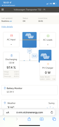
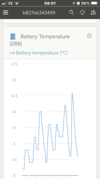
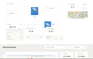
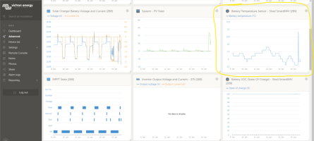
@Samro, yes the temp sensor are two types. This one is ve bus type. It’s wired on the multiplus temp sense pins. It sends data via the mk3 interface to RPi. If I would had a cerbo or venus,, it would send data via UTP rg45 cable. The bit you probably missing is the mk3 interface, that converts ve bus to usb. I do see the temp in the vrm, under advanced. There you pick relevant widgets to be displayed. Here is a screenshot of mine.
DF89397D-89C9-40B5-9E80-54A89695868B.png
The BT battery sense networked with the solar chargers, will not show on vrm. At least I didn’t managed. But the multiplus one does, as above.
 
@Dellmassive, thank you for your compliments. I know ppl have different needs, this is tailored to our needs after few upgrades. We learned the hard way that, buy cheap buy twice, there is no such think as to much solar, buy once cry once; the T6 would be way to small for us, so we skipped straight to a crafter. There might be a caddy maxi later, for different purposes.
 
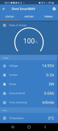
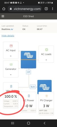
I'm wondering about my temp data on VRM....?

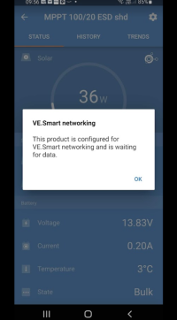
I have the temp from the internal MPPT, (Sampled once a day apparently)

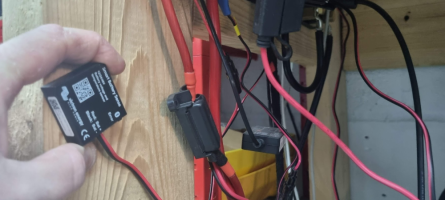
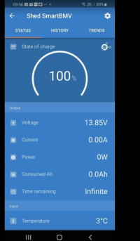
But also have the black Bluetooth battery Sence sharing data to the BMV712...?

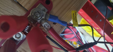
But also have the blue temp sensor hard wired into the BMV712.

So 3 possible sources of temp data.

I'll have to test later with some freeze spray... (Lynx Africa lol. )

Screenshot_20220113-085150.jpgScreenshot_20220113-085113.jpg

Screenshot_20220113-084730_Chrome~2.jpg


More details here -


.
 
Interesting, I don’t get the temp sensor on the solar charger in the vrm. Only on local blue tooth shows. The one you circled is the bmv712 sensor. Hence comes under batt monitor window. That is not far of the ve bus sensor. It uses the bmv 712 pcb to send data. The 700 (my case), misses that hardware, hence I had to use a ve bus option.
 
Interesting, I don’t get the temp sensor on the solar charger in the vrm. Only on local blue tooth shows. The one you circled is the bmv712 sensor. Hence comes under batt monitor window. That is not far of the ve bus sensor. It uses the bmv 712 pcb to send data. The 700 (my case), misses that hardware, hence I had to use a ve bus option.

Victron don't seem very joined up on the way in which battery temp data is used in the VE networking.

I have temp data showing on the VRM for my caravan setup, where I am using temp sensors plugged directly into the temp input ports of the Venus GX device. This data is not displayed on the VRM in the same way as shown @Dellmassive screenshot though. (I know that my temp data, on the VRM, is not considered by the charger or the MPPT and therefore I used Smart Sense sensors which were required to account for this.)

This is because it seems that Victron stupidly don't allow the networking of GX device to control the charge of MPPT's or other charging devices. (Unless a Multiplus.) So the usefulness of the standard temp sensors is simply to allow me to view the temperatures at the caravan remotely. Up until today i understood that the temp data from the Smart Sense's could not be viewed through the GX gateway (on the VRM).

My temp data is displayed very differently to @Dellmassive screenshots above, (on the VRM) as my data is coming directly from the Gateway and not a BMV-712.

The temp data that is shown in the above screenshot from @Dellmassive clearly exists due to the BVM712 receiving Bluetooth data from the battery sense. I only have BMV-700 on the caravan and in hindsight this was a mistake at the time of installation!)
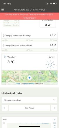
cold venus.jpg
(Batteries are 10.07V. The temp is preventing the mppt's from providing any charge! I will sort this weekend.)

So @Dellmassive 's post is actually a revelation to me as it demonstrates that the BMV-712 is superior to the BMV-700 insofar that it communicates Smart Sense data to the VRM via the GX Gateway. I didn't know that, as I assumed that the BMV-700 and the Smartshunt products would behave in the same way as the BMV-712 as they are all joined to the same VE network.

My initial query was in relation to my Van setup and thanks for your response @Raul a/3 :
@Samro, yes the temp sensor are two types. This one is ve bus type. It’s wired on the multiplus temp sense pins. It sends data via the mk3 interface to RPi. If I would had a cerbo or venus,, it would send data via UTP rg45 cable. The bit you probably missing is the mk3 interface, that converts ve bus to usb. I do see the temp in the vrm, under advanced. There you pick relevant widgets to be displayed. Here is a screenshot of mine.

I understand that the Mk3 interface essentially converts data from the RJ45 input to USB to input to the rpi.

Without a Multiplus I cannot see how the temp sensor can communicate using a RJ45 connection? The standard (type C) temp sensor is usually connected directly to the Cerbo GX (or Venus GX) gateway, and without a suitable port on the rpi, I am unsure of how i could get temp from a sensor like the one below and get the data on the network?
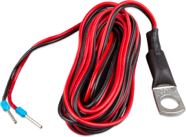
Temp Sense.png
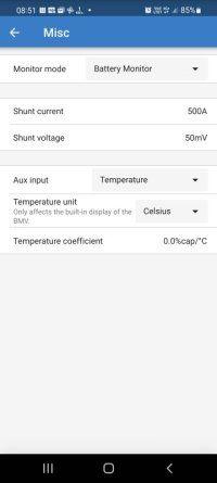
You can see from the below screen shots (from my van) that the Smart Sense, battery monitor and mppt are talking to one another, but the info will not show across the VRM whatever I do.
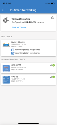
VAN BAT MON.png van vrm.png

Why Victron have not included VE network compatibility between the Smart Sense and the BMV-700 (Installed on my Caravan), or the SmartShunt 500A (Installed in my van) is beyond me. (They sort of half heartedly have, but it is not available on the VRM!)

Edit: In summary:
@Raul a/3's system is presenting its temp data to the VRM from the Multiplus Widget.
@Dellmassive's system is presenting its temp data to the VRM from the BMV-712 Widget.
My Caravan is presenting its battery temp data from a sensor connected to a Venus GX gateway Widget.
My T6 is not able to present its temp data to the VRM at all because i cant plug a temp sensor into raspberry pi!
 
I understand you pain. Victron has made a step in this direction, to enable the getaway to control the chargers. Not the temp yet. They implemented the DVCC dinamic voltage and current control. It controls the charging. You can set the limit in the getaway and It controls the charge. Before the charger will not know where the power goes: to the battery or loads. If you had a limit of 30a charger could not differentiate if that production goes to battery or is eaten by loads. Now with DVCC active, and the bmv shunt, can work what’s going on the battery, and preventing the chargers throttling back allowing to sustain the load to. Hope that makes sense. I hope in future they will implement new features. Like you, I have two bmv700 but also multiplus . My second installation is the off grid house. In there I have 160a solar charging, but batteries can only take max 70a. So I activated the DVCC, and the solar is not limited to 70a anymore, if oven or workshop eats the power. I can have a peak of 6-7kw production, with 3,5kw going to battery and the rest to loads. Without DVCC, this was not possible, you had to limit the amps on the charger.
 
@Raul a/3 @Samro

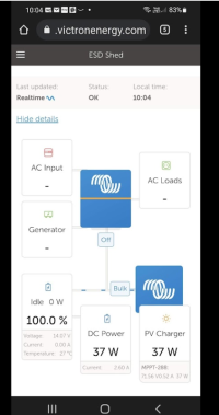
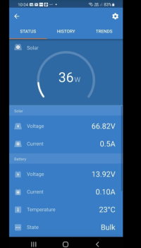
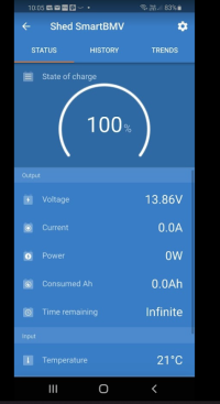
just went out and done some testing. - regards to Temp reporting on VRM

setup:
2x SLA LB
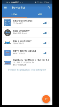
BMV712 (BT+VE direct USB) + Blue temp sense
Black Smart Battery sense (BT)
MPPT 100/20 (BT+ VE Direct USB)
RPi with Venus - Online
Plus other bits, but not important for this test

i have the Blue temp sensor connected to a BMV712, and a Black Smart battery sense.

1642154851509.png1642154864366.png1642154872170.png

with this MPPT.

1642155093267.png


.

this Rpi

1642155115647.png

.
and BMV712

1642155137749.png

++++++

local BT scan shows these devices:

1642155170869.png
.................

Temps:

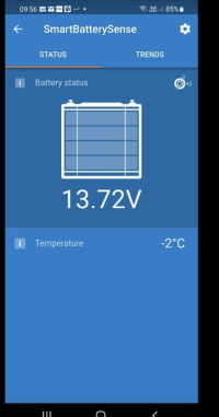
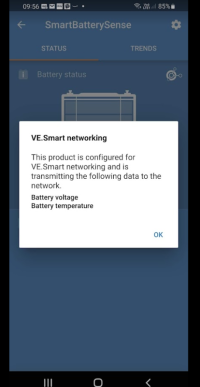
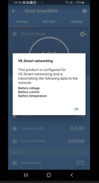
The smart battery sense shows -3degc, and shows sharing the temp data via BT


1642155194752.png1642155233276.png

.

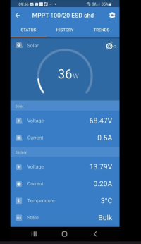
the MPPT shows +3degc

1642155218311.png1642155261735.png


.

the BMV712 shows +3degC
1642155288508.png1642155301051.png

.


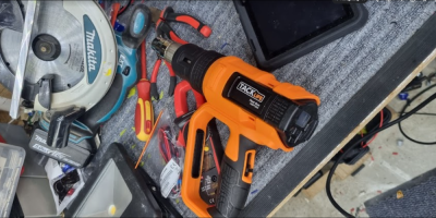
i used this heat gun to heat up JUST the blue temp sensor on the BMV712.

1642155341897.png


.

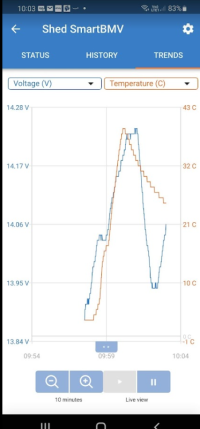
which gave me this as expected on the BMV temp plot . .

1642155371890.png

.

VRM now also follows the BM7temp data . . . +27degc at this point.
1642155423095.png


..


moving to local BT . . .

The solar MPPT is now showing +23degC . . .

1642155477109.png

as is the BMV . . . +21degc . .

1642155503158.png

.


so it looks like on my setup the Temp data is coming from the blue temp sensor on the BMV712.

it looks like the "smart battery sense" isn't doing much.

and the MPPT is using the BMV712 temp data and ignoring its own interal temp sensor (sampled once a day apparently)


.


20mins later . . . VRM shows temp down to +8degC (ambient is +3degc)


1642155695955.png


.
 
@Dellmassive, if you look back few posts above Samro posting, I did mention, your vrm temp display comes in the bmv window widget. That means, it’s the bmv712 that sends that data. The 721 has diferent pcb and additional hardare components on pcb that enables to send that extra data.
Nice test and I appreciate the time for doing it, and share it. The solar charger internal temp sensor is used all the time if: you have temp compensated charging enabled. The one sample in the morning is taken only when temp compensation is disabled. Also one voltage sample is taken in the morning to estimate absorbtion time. As suspected, the temp battery sense Bluetooth sensors are only used local, and this data is not sent to vrm, YET. I think will be a transition at some point, as I see some ve direct inverters in the offerings. There’s still a need for ve bus sensors, lots of Quattro’s and multi’s need them. The multiplus 2 is accredited for feed in as well, so I don’t see they will ditch those sensors. One think for sure, ve direct is taking up, with cerbo, octo lots of ports, would be nice to have a B2B with ve direct port.
 
@Raul a/3 - yep gotcha.

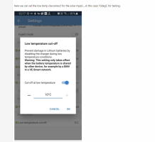
i did some previous testing with charging Lithium's at low temp, and the low temp cut off using the BMV712.


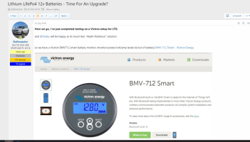
temp sensors mentioned here: Lithium LifePo4 12v Batteries - Time For An Upgrade?


and testing tried here: Lithium LifePo4 12v Batteries - Time For An Upgrade?


1642167420149.png


Thats about it.

The solar on the roof charges the battery via the MTTP.
The power in/out is monitored via the BMV
you can add your DC-DC as per below.

Now the cleaver bit, you create a VE-Direct bluetooth network via the Victron app, this enables the BMV to report the battery bank voltage and temp to the MPPT wireless via bluetooth..


The solar MPPT has its own setting in the lithium profile that you can now set the LTD point . . . say 5degC, so at that point the MPPT will stop charging the battery. (Solar MPPT LTD done!)


But what about my DC-DC charger? - how do i stop that from charging my batterys when cold? . . . . Well the BMV has a latching relay on the back of the display.
This can be set to do many things, but in out case we are setting it to be a LTD (this is a separate setting/adjustment to the mppt and works independently).

We set the alarm relay to open at below 4degC and to close again above 6degC (you can set whatever limits) we can now use this relay to interrupt the turn on signal for our DC-DC charger.
in our case its a Redarc BCDC charger that requires a ignition/run feed to start working. . . . . so if its to cold the BMV will keep the BCDC off untill the temp rises (by disabling the ignition feed to the dc-dc). (DC-DC LTD Done!)

No external cheap temp PCB`s, no external SCR or contractors, nothing get disconnected and no messing about . . . . . . . just a BMV (with temp), MTTP, DCDC


Now, as for a LBD, thats easy, just buy a victron battery protect unit and set it to 11.5v disconnect then wire between the loads and +v battery terminal - but ill show that a different day.


1642167511066.png


.
 
Nice, to summarise, if you have a bmv712 with temp sensor, the charger does not need a Bluetooth battery sense stuck on. Even better, since bmv reports what’s going on the battery, the charger is allowed to harvest just enough to sustain loads but not over to go to battery?
 
Nice, to summarise, if you have a bmv712 with temp sensor, the charger does not need a Bluetooth battery sense stuck on. Even better, since bmv reports what’s going on the battery, the charger is allowed to harvest just enough to sustain loads but not over to go to battery?
That is exactly what I was trying to say in my previous overly long post!
I am a bit peeved with Victron as I can't see why their BMV700 or the Smartshunt behave differently to the BNV712.

It is now clear that I misunderstood, as I thought that the BMV700 was the same as the BMV712 when I specced my caravan install. (with the exception of built in Bluetooth and Aux battery input.) I obviously only have a single battery bank on a caravan and the monitor is hard wired to the VE network, so why specify a BMV712?.....I thought!
So when I specced the van, I knew I needed an aux input for the van battery and wanted bluetooth, so I bought the Smartshunt as I understood it to be identical to the BMV712, without a physical display.

So, in short all I can say is Bugger!

By the way, it was my intention to get the VRM displayed on the vans infotainment screen, hence me considering the smartshunt ideal for the job. Trouble is I need to jailbreak my phone to do this and I can't jailbreak my iPhone because it is running iOS 15.1.
Anyone know of a way to display the Victron app on the infotainment screen using Apple Carplay?
 
Back
Top