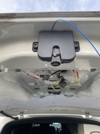
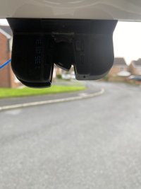
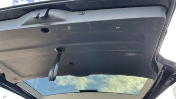
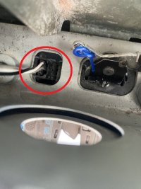
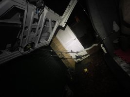
The child lock switch is in your picture, post #305, well, the back of it is, its near the latch, you can only access it when the tailgate is open, you use your key to operate it.
Hi I’ve had a good look and can’t see anything and really don’t understand where the child lock is on the tailgate if at all ?

IMG_8668.jpeg

IMG_8669.jpeg
 
You may not have it if there isnt an internal release switch.
View attachment 263220
Its not somthing i have.

I really dont know what else to do and its drving me crazy. I have also copied all your settings in the vcds which didnt change anything.

So until someone who has had the same problem as me. Which is simply that it works as intended only when the latch is on the first setting or ajar. If the van is unlocked you can press the handle and the acuator powers and will open the tailgate. I can also use the test function in the vcds at this stage and it will also open the tail gate. But when i close the tailgate fully onto the second latch if you will. NOTHING cant open from the vcds nor from the handle. The child lock thing was a good idea but iam again stumped completely.

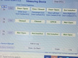
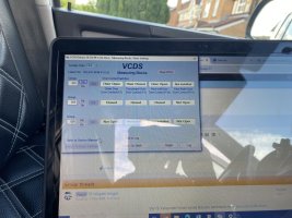
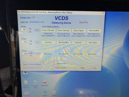
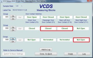
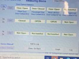
One thing i that hasnt been anwsered is the message blocks when testing the latch etc mine look different to in the guide. I have a message box that states not installed. Do you see the same in the message blocks as the guide or like mine ?

IMG_8580.jpeg

09-Rear lid-Meas.Blocks_a.jpg
 
  • Wow
Reactions: mmi
One thing i that hasnt been anwsered is the message blocks when testing the latch etc mine look different to in the guide. I have a message box that states not installed. Do you see the same in the message blocks as the guide or like mine ?
1729531758739.png
The "uninstalled" there is very weird.


Based on the yesterday's Auto-Scans the faults below appeared when you changed the coding as proposed (for actual tailgate coding).
Code:
The first scan (post #310) didn't have these faults. Then scan after the changes in post #312 has these.

00329 - Control Circuit for Unlocking Rear Lid
            006 - Short to Plus - Intermittent

00329 - Control Circuit for Unlocking Rear Lid
            011 - Open Circuit

Would always be helpful to have full VCDS Auto-Scan as text.

At first glance you need to change the following BCM codings:
byte 1 - change from FC --> A8
byte 2 - change from 09 --> 39
byte 7 - change from 31 --> 11

byte 0 - change from EE --> 62 (if you do not have safe-lock), or EE --> A0 (if you have safe-lock)
verify everything works and then separately adjust Auto-Lock & Auto-Unlock functionalities (bits 3&4)

Would the faults possibly suggest there is something wrong with the wiring??
 
I really dont know what else to do and its drving me crazy. I have also copied all your settings in the vcds which didnt change anything.
Just to double-check the BCM codings and BCM adaptations please post

(1) BCM adaptation map
(2) BCM block map


The below should work IGNition OFF

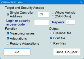
VCDS > Applications > Controller Channel Map >

1729534975958.png
Tick/fill boxes as above and click Go.

VCDS flashes screens for a moment (when finished hit "Done, Go Back") and there should be files blockmap-09-... and adpmap-09... in folder C:\Ross-Tech\VCDS\Logs\....
 
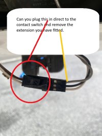
Can you remove this wire and connect the original plug directly. Looking at this you can see with the extra extensions in they cross over, pin 2 on the main harness is ground (middle one) with these wires in it is putting it on the trigger sides of the switch (pins 1 and 3, the outer white wires are for open and ajar).

this1.jpg

this2.jpg
 
Just to double-check the BCM codings and BCM adaptations please post

(1) BCM adaptation map
(2) BCM block map


The below should work IGNition OFF

VCDS > Applications > Controller Channel Map >

Tick/fill boxes as above and click Go.

VCDS flashes screens for a moment (when finished hit "Done, Go Back") and there should be files blockmap-09-... and adpmap-09... in folder C:\Ross-Tech\VCDS\Logs\....
 

Attachments

  • adpmap-09-7E0-937-090-B-20241022-1206.CSV
    339 bytes · Views: 2
  • blockmap-09-7E0-937-090-B-20241022-1205.CSV
    2.3 KB · Views: 1
First of all thanks to everyone who has contributed. I think a little progress has been made by eagle eyes. so thank you. Todays findings are worth a mention.

So today I did as you asked and plugged the connector directly into the latch and found the following would only display on the measuring blocks.

When the connector is plugged directly into the latch as it should be.


I get open open when fully open. On vcds. Nothing from handle


I get closed closed on the first latch. On vcds .Nothing from the handle


I get closed closed on second latch. On vcds . Nothing from the handle


So again to test I installed another little jumper wire to test each wire (in the photo for reference) and response to the vcds and see what it registers. It seems that the latch isn’t doing this correctly. However no closed reading allows me to use the handle

On the tailgate to open the tailgate.


So here are my findings.


Closed closed when no wires are connected together at all


Open closed brown wire and the red wire connected. Handle operates and registers activated on vcds measuring blocks


Open open when both pins are connected to earth pin. So the brown and orange are connected to the red. Nothing from the handle.


Closed closed when orange wire is connected to red. Nothing from the handle.


Closed open when brown and orange are connected. Nothing from the handle


The only way I can get it to work is to simple connect the brown and red together.

The van state is open closed on the vcds. It will

Open when van is unlocked from

The handle but not when I lock the van. So it appears to be working. But shows the door as open in the vcds and also icon shows on the dash that a doors open.


Continuity check that the middle pin in the connector is earth with another earth in the tailgate. Get continuity so ( brown in the connector )is earth as it should be.


Now referring to the jumper wire colours :

The orange wire to earth showed resistance of 1230 on multi meter. The brown wire to earth shows no continuity.
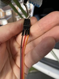
IMG_8681.jpeg

IMG_8680.jpeg

IMG_8678.jpeg

IMG_8675.jpeg

IMG_8676.jpeg
 
For reference, the 3 pin plug you have in the picture Pin 1 (white) is the wire for registering door contact. Pin 2 (brown) is directly connected to ground. Pin 3 (white) is the interior light contact switch.

Do you get continuity from the ground connection (any on the tailgate) to a ground on the van with the tailgate open? what I'm thinking is the tailgate has no ground, other than when it is fully closed and picking up a ground via the striker?
 
Last edited:
Hi thanks for the response. So I am doing all the tests with the tailgate open and manually locking the latch. It’s quite easy to engage and disengage. So it’s not getting ground from striker plate. Also you say pin 3 is for the interior light ? Which light exactly ?

I just can’t seem to understand from following the instructions of the guide. When my message blocks display closed the handle becomes unresponsive. It makes no sense to me.
 
The lights in the roof panel. The ones that come on when you open the doors.
Im at a loss now without physically being there i can't think what the problems could be.
What is your current long coding for the bcm 09?
 
Hi anyone done the conversion recently ,and got a total price on doing it? I'm looking for a new van but need a tailgate , just waying up tailgate conversion costs.cheers
 
Hi all about to start my barn door to tailgate swap, can anyone confirm the routing of the pipe/hose supply from washer bottle to tailgate for the rear wash wipe..I can see its part of the tailgate loom then connects to rest of the feed pipe which will route with the main wiring loom along left hand of roof towards front of the van.

How does it get from the roof a pillar area into the engine bay please ?

I want it to look as factory fitted as possible !
Tia
 
Hi guys, firstly I wish I had read more than the first few pages of this thread before I went ahead of the conversion! Due to the peeps having the stress cracks. Everything else has gone smoothly.


So my model is a T6.1 and just wanting to know if I’ve missed something; with the wiring I just hooked up the old barn door loom to the tailgate and everything worked. Only thing I had to do is reverse the polarity going to the unlock solenoid. The boot release from the barn even worked when there wasn’t one on the tailgate loom. So is the T6.1 different because I thought I was going to have to run cables back to the BCM?


Only annoyance left are the LED number plate lights are throwing an error and the I need to change the struts. Hoping as has been discussed the T5 ones will be long enough!


Picture for illustration purposes:

IMG_0957.jpeg
 
Hi guys, firstly I wish I had read more than the first few pages of this thread before I went ahead of the conversion! Due to the peeps having the stress cracks. Everything else has gone smoothly.


So my model is a T6.1 and just wanting to know if I’ve missed something; with the wiring I just hooked up the old barn door loom to the tailgate and everything worked. Only thing I had to do is reverse the polarity going to the unlock solenoid. The boot release from the barn even worked when there wasn’t one on the tailgate loom. So is the T6.1 different because I thought I was going to have to run cables back to the BCM?


Only annoyance left are the LED number plate lights are throwing an error and the I need to change the struts. Hoping as has been discussed the T5 ones will be long enough!


Picture for illustration purposes:

View attachment 267244
I would have expected you needed the extra two wires as barn doors are a mechanical handle. 6.1’s may be different.

The T5 struts should be fine.
 
Back
Top