DC-DC Charger (for Leisure battery) -- How I Done It --
**************************************************
Dellmassive`s -- "how I Done It" -- Thread
**************************************************
Kit List And Stuff -- How I Done It & What I Use --
**************************************************
I thought it was about time i addressed the whole DC-DC charger thing. . . .
The subject and viability is discussed at length over here > Stop/start...regen...smart Alternator... Dc-dc Charger For Leisure Battery Or Not?
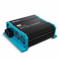
Long story short the conclusion was that if you want a decent Leisure battery setup that will last a weekend, week, month etc etc ...... Then you need a DC-DC charger.
why?
Well as we found out VW went for the option of a SCR (Split Charge Relay), which worked fine for all of history before "EU6 engines with stop/start"(and EU5 T6 with stop/start as highlighted below) . . . . this new engine tech changed everything! Not only on the VW T6 but but all vehicles from all manufacturers..... Even the trusted converters got caught on the hop.
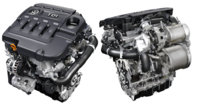
The reason for this change is "emissions standards" and MPG/fuel economy . . . the clever guys at say VW worked out that if you used the kinetic energy from deceleration/braking to "charge" the battery then you didn't need to waist precious fuel and MPG`s while driving. . . . . the net effect is that the alternator is mostly free-wheeling and only dumps power into the battery when braking.
Now this is an extremely simplified version of events .. . . in truth there is a very complex system of electronics, sensors and software controlling the whole process to ensure that we dont end up with a flat battery on Monday morning.
*****************************************************************************
What does it do?
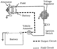
The old "pre-EU6" system ensured a constant supply of power from the alternator when the engine was running . . . this could be seen with a multi-meter and would show a healthy 13.8v constantly that would charge the starter battery as well as any leisure battery/s that were connected to the system via the SCR. . . . This has worked great for years.
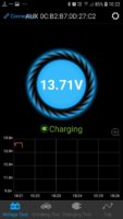
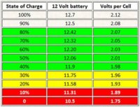
In the EU6 stop/start setup its all different, the alternator mostly free-wheels and will develop chunks of power under braking or as needed, all controlled by a computer ECU. . . . you can see this with a multi-meter, you will see 12.6v battery voltage rising to 15.2v under braking then dropping back to 12.6v when accelerating. . . . .this is no good for charging your leisure battery via a SCR.
The Ideas is the ECU will keep the starter battery at around 80% full to leave room for the REGEN braking . . .this all helps MPG and emissions. when you then connect your leisure battery and a SCR to the system you will find that your leisure battery will only ever achieve 80% SOC (state of charge) and that can fluctuate wildly (and thats assuming you are driving long enough to let the battery absorb the charge), also there is and issue of back drain . . . where by your 100% solar charged leisure battery will effectively drain its-self back down into the starter battery via the SCR once the van starts. (that has just wasted all your solar harvest)
The issue being is that in a leisure situation on a SLA (sealed lead acid) battery, you can only use the the top 50% of the battery power, its referred to a 50% DOD (depth of discharge) . . . it means on a 100Ah battery you can only use 50ah . . . beyond this the voltage drops too low to be usable and battery damage can occur... that means that if your leisure battery is only 80% charged in the first place . . . . and you can only use 50% . . . then you end up with 30% or less of your battery for your leisure applications . . . . . (this is not good and why your battery wont run your fridge and LED lights for a 3day camping trip =[ )
*****************************************************************************
A DC-DC charger will totally separate your starter battery and leisure battery systems to prevent these problems.
They work very similar to the SOLAR MPPT controllers . . . they have internal boost and buck converters that can reduce or increase the voltage/power coming from the engine bay...
Now "power is power" (that means it cant be created, but can be changed) and thats physics but what these cleaver boxes will do is take the lower voltage 80%(SOC @13.2v Float) starter battery and boost the voltage to a decent charge for your leisure setup (>100% 14.2v bst/abs/flt) . . .
They will also reduce the massive surge from the regen phase to a voltage (15.2v regen) suitable for charging.... effectively they will take the massively changing voltages a EU6 engine produces and turns it into a stable steady charging voltage to keep you leisure system at 100% charged. (>100% 14.2v bst/abs then drop to 13.2v flt as per the selected charge smart algorithm)
The great thing is these work like standard EHU battery chargers . . . they have smart 3-7 stage charging algorithms including Lithium, that will constantly monitor the SOC of your leisure setup and keep it charged to 100%. They have many built in safety features and are basically fit and forget units. . . . . Some units even have built in Solar MPPT charge controllers that offer a one-stop-shop charge solution. . . . .
Then once the battery is fully charged, the DC-DC will drop to float/maintenance mode to keep the battery at 100%.
*****************************************************************************
What happens when i turn on my Camper loads? (Inverter, Kettle, Lights, heater) -
well this is the cleaver part, most DC-DC chargers will disconnect the charging power every so often (every 100sec in the case of Redarc) to "sample" the AUX battery voltage, They use this data combined with the Current thats being drawn to determine the SOC of the battery or the Loads that are connected to the battery. . . . When you draw Loads or current from the AUX battery it will cause a slight volt drop that the DC-DC charger will detect. Using this reading plus the current drawn from the charger will make the charger move into full charge mode in an attempt to keep the battery fully charged.
The net effect is that even if your AUX battery is 100% charged @ 12.6V and the engine is running . . . . . when you switch on your loads the DC-DC charger will raise the output voltage to 14.6v or so and deliver up-to its maximum current... So effectively all your loads are being powered from the DC-DC charger and no battery power is lost (until you switch off the engine that is)
*****************************************************************************
What size DC-DC charger do i need?
This is a good question, and the answer is very similar to the "what size solar do i need?" . . . Its not just about charging your battery . . . . its also about charging you battery WHILE running your loads. So you need to account for your worst case scenario - which will be a low AUX battery while remote camping while running all your loads - at nighttime - in the rain - and its snowing etc etc ..
Joking aside i believe that the sizing of a DC-DC should account for the above, whats the point in getting in that situation, then having to switch off all your lights and fridges etc . . . just to give the battery as much charge as possible while running the engine for 20mins at nights . . . . . nope thats not right.
So take your AUX battery size say 100Ah and go with 10-20% which is a recomended charge rate for SLA/AGM etc - thats 10-20A charger .
Then measure all your loads, either with a current clamp meter, or add up all your Watts or any other way get an idea of what your worst case scenario is . . . an example may be 6amp, 10amp, 15amp, 20amp . . . whatever. Lets take 10Amp for thius example.
Add the Battery charge rate of 10-20A plus the Loads draw rate of 10A give you a figure of 20-30A.
Now you know that a 30A DC-DC is needed to fully charge your AUX battery while drawing a Load.
If you are a POWER USER like me then the sky is the limit . . . . i have 1000-1500W inverters that will draw 100A easy frona SLA/AGM battery which causes large volt SAG and depleates the battery rapidly . . . im my case i use DC-DC to offset the current draw from the battery . . . . So ill draw say 40A from the DC-DC charger, then the rest from the Aux battery. - doubling up DC-DC chargers in parrallel is also posdsible so 2x 40A DC-DC chargers will give 80A then only 20A will be drawn from the battery. (remember the cables on the system will need to handle the 80A current)
********************************************************************
What are the smart charger stages?
Adaptive three step charging, DC-DC chargers are configured for a three-step (or more) charging process: Bulk – Absorption – Float.
Bulk During this stage the controller delivers as much charge current as possible to rapidly recharge the batteries.
Absorption When the battery voltage reaches the absorption voltage setting, the controller switches to constant voltage mode. For lead acid batteries it is important that during shallow discharges the absorption time is kept short in order to prevent overcharging of the battery. After a deep discharge the absorption time is automatically increased to make sure that the battery is 3 EN NL FR DE ES SE IT completely recharged. For lithium batteries absorption time may be limited. The fixed or adaptive mode can be chosen on the battery settings (Victron unit).
Float During this stage, float voltage is applied to the battery to maintain it in a fully charged state. When the battery voltage drops substantially below this level, due to a high load for example, during at least 1 minute, a new charge cycle will be triggered.
*********************************************************************
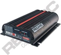
Next is to look at the available DC-DC chargers and they can/cant do:
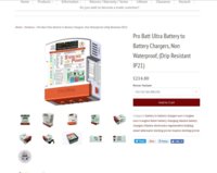
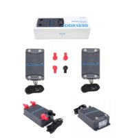
The main contenders are below:
CTEK
REDARC
ABLEMAIL
VOTRONIC
there are other makes around.
**************************************************************
The things to look for in a DC-DC or B2b charger are:
- Max though-put or charging Amps ie 20/30/40/50/60 A.
- input voltage range ie 10-16V input for start/stop engines.
- output voltage ie - 12v as some are 24v or even 36V.
- Battery types they work with ie - AGM, SLA,LIFEPO4, Gell.
- Multi-stage smart Charging? - most are.
- Does it have a temp sensor? - some do, some dont.
- type/size of input/output terminals..
- Does it have a MPPT solar reg built in? - some do, some dont..
- can they be parralled up for power users? (some can have 4x in parrallel).
*************************************************************
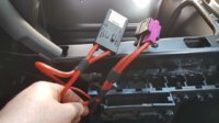
The T6 "Engine Run" feed from the BCM is shown here:

T6 - Second battery wiring diagram
Second battery for transporter ( not California)
 www.t6forum.com
+12v switched on when RPM engine run is detected.
used by the OEM setup to switch a 80A relay that connects the second battery (old skool SCR)

conection : J519 BCM - T73a/3
*************************************************************
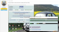
And BCM coding to activate output:
credit: @Deaky - Byte 17 Bit 4 Battery Seperating Relay active

credit: @rod_vw
**************************************************************
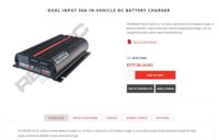
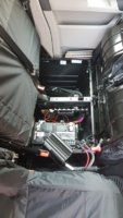
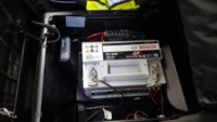
I personally have been running the Redarc BCDC1240LV,
and will be upgrading to the BCDC1250D shortly (added Lifepo4 battery + 50A throughput)
I will also be getting a Victron 12/12/30 to test (to see if it will work with VE-Direct)
***************************************************************
Diagrams, Schematics & Wires -- How I Done It --
***************************************************************
EDIT:
I've started a excel sheet detailing the most important details of the various DC-DC charger units as an easy to read chart.
I've attached the sheet below to download, if you have any of the missing DC-DC chargers or want to add your own . . .
download the chart edit/add in your own unit then email it back to me for uploading : [email protected]
******************

*****************
**************************************************
Dellmassive`s -- "how I Done It" -- Thread
**************************************************
Kit List And Stuff -- How I Done It & What I Use --
**************************************************
I thought it was about time i addressed the whole DC-DC charger thing. . . .
The subject and viability is discussed at length over here > Stop/start...regen...smart Alternator... Dc-dc Charger For Leisure Battery Or Not?

Long story short the conclusion was that if you want a decent Leisure battery setup that will last a weekend, week, month etc etc ...... Then you need a DC-DC charger.
why?
Well as we found out VW went for the option of a SCR (Split Charge Relay), which worked fine for all of history before "EU6 engines with stop/start"(and EU5 T6 with stop/start as highlighted below) . . . . this new engine tech changed everything! Not only on the VW T6 but but all vehicles from all manufacturers..... Even the trusted converters got caught on the hop.

The reason for this change is "emissions standards" and MPG/fuel economy . . . the clever guys at say VW worked out that if you used the kinetic energy from deceleration/braking to "charge" the battery then you didn't need to waist precious fuel and MPG`s while driving. . . . . the net effect is that the alternator is mostly free-wheeling and only dumps power into the battery when braking.
Now this is an extremely simplified version of events .. . . in truth there is a very complex system of electronics, sensors and software controlling the whole process to ensure that we dont end up with a flat battery on Monday morning.

*****************************************************************************
What does it do?
The old "pre-EU6" system ensured a constant supply of power from the alternator when the engine was running . . . this could be seen with a multi-meter and would show a healthy 13.8v constantly that would charge the starter battery as well as any leisure battery/s that were connected to the system via the SCR. . . . This has worked great for years.

In the EU6 stop/start setup its all different, the alternator mostly free-wheels and will develop chunks of power under braking or as needed, all controlled by a computer ECU. . . . you can see this with a multi-meter, you will see 12.6v battery voltage rising to 15.2v under braking then dropping back to 12.6v when accelerating. . . . .this is no good for charging your leisure battery via a SCR.
The Ideas is the ECU will keep the starter battery at around 80% full to leave room for the REGEN braking . . .this all helps MPG and emissions. when you then connect your leisure battery and a SCR to the system you will find that your leisure battery will only ever achieve 80% SOC (state of charge) and that can fluctuate wildly (and thats assuming you are driving long enough to let the battery absorb the charge), also there is and issue of back drain . . . where by your 100% solar charged leisure battery will effectively drain its-self back down into the starter battery via the SCR once the van starts. (that has just wasted all your solar harvest)
The issue being is that in a leisure situation on a SLA (sealed lead acid) battery, you can only use the the top 50% of the battery power, its referred to a 50% DOD (depth of discharge) . . . it means on a 100Ah battery you can only use 50ah . . . beyond this the voltage drops too low to be usable and battery damage can occur... that means that if your leisure battery is only 80% charged in the first place . . . . and you can only use 50% . . . then you end up with 30% or less of your battery for your leisure applications . . . . . (this is not good and why your battery wont run your fridge and LED lights for a 3day camping trip =[ )

*****************************************************************************
A DC-DC charger will totally separate your starter battery and leisure battery systems to prevent these problems.
They work very similar to the SOLAR MPPT controllers . . . they have internal boost and buck converters that can reduce or increase the voltage/power coming from the engine bay...
Now "power is power" (that means it cant be created, but can be changed) and thats physics but what these cleaver boxes will do is take the lower voltage 80%(SOC @13.2v Float) starter battery and boost the voltage to a decent charge for your leisure setup (>100% 14.2v bst/abs/flt) . . .
They will also reduce the massive surge from the regen phase to a voltage (15.2v regen) suitable for charging.... effectively they will take the massively changing voltages a EU6 engine produces and turns it into a stable steady charging voltage to keep you leisure system at 100% charged. (>100% 14.2v bst/abs then drop to 13.2v flt as per the selected charge smart algorithm)
The great thing is these work like standard EHU battery chargers . . . they have smart 3-7 stage charging algorithms including Lithium, that will constantly monitor the SOC of your leisure setup and keep it charged to 100%. They have many built in safety features and are basically fit and forget units. . . . . Some units even have built in Solar MPPT charge controllers that offer a one-stop-shop charge solution. . . . .
Then once the battery is fully charged, the DC-DC will drop to float/maintenance mode to keep the battery at 100%.
*****************************************************************************
What happens when i turn on my Camper loads? (Inverter, Kettle, Lights, heater) -
well this is the cleaver part, most DC-DC chargers will disconnect the charging power every so often (every 100sec in the case of Redarc) to "sample" the AUX battery voltage, They use this data combined with the Current thats being drawn to determine the SOC of the battery or the Loads that are connected to the battery. . . . When you draw Loads or current from the AUX battery it will cause a slight volt drop that the DC-DC charger will detect. Using this reading plus the current drawn from the charger will make the charger move into full charge mode in an attempt to keep the battery fully charged.
The net effect is that even if your AUX battery is 100% charged @ 12.6V and the engine is running . . . . . when you switch on your loads the DC-DC charger will raise the output voltage to 14.6v or so and deliver up-to its maximum current... So effectively all your loads are being powered from the DC-DC charger and no battery power is lost (until you switch off the engine that is)
*****************************************************************************
What size DC-DC charger do i need?
This is a good question, and the answer is very similar to the "what size solar do i need?" . . . Its not just about charging your battery . . . . its also about charging you battery WHILE running your loads. So you need to account for your worst case scenario - which will be a low AUX battery while remote camping while running all your loads - at nighttime - in the rain - and its snowing etc etc ..
Joking aside i believe that the sizing of a DC-DC should account for the above, whats the point in getting in that situation, then having to switch off all your lights and fridges etc . . . just to give the battery as much charge as possible while running the engine for 20mins at nights . . . . . nope thats not right.
So take your AUX battery size say 100Ah and go with 10-20% which is a recomended charge rate for SLA/AGM etc - thats 10-20A charger .
Then measure all your loads, either with a current clamp meter, or add up all your Watts or any other way get an idea of what your worst case scenario is . . . an example may be 6amp, 10amp, 15amp, 20amp . . . whatever. Lets take 10Amp for thius example.
Add the Battery charge rate of 10-20A plus the Loads draw rate of 10A give you a figure of 20-30A.
Now you know that a 30A DC-DC is needed to fully charge your AUX battery while drawing a Load.
If you are a POWER USER like me then the sky is the limit . . . . i have 1000-1500W inverters that will draw 100A easy frona SLA/AGM battery which causes large volt SAG and depleates the battery rapidly . . . im my case i use DC-DC to offset the current draw from the battery . . . . So ill draw say 40A from the DC-DC charger, then the rest from the Aux battery. - doubling up DC-DC chargers in parrallel is also posdsible so 2x 40A DC-DC chargers will give 80A then only 20A will be drawn from the battery. (remember the cables on the system will need to handle the 80A current)
********************************************************************
What are the smart charger stages?
Adaptive three step charging, DC-DC chargers are configured for a three-step (or more) charging process: Bulk – Absorption – Float.
Bulk During this stage the controller delivers as much charge current as possible to rapidly recharge the batteries.
Absorption When the battery voltage reaches the absorption voltage setting, the controller switches to constant voltage mode. For lead acid batteries it is important that during shallow discharges the absorption time is kept short in order to prevent overcharging of the battery. After a deep discharge the absorption time is automatically increased to make sure that the battery is 3 EN NL FR DE ES SE IT completely recharged. For lithium batteries absorption time may be limited. The fixed or adaptive mode can be chosen on the battery settings (Victron unit).
Float During this stage, float voltage is applied to the battery to maintain it in a fully charged state. When the battery voltage drops substantially below this level, due to a high load for example, during at least 1 minute, a new charge cycle will be triggered.
*********************************************************************

Next is to look at the available DC-DC chargers and they can/cant do:
The main contenders are below:
CTEK
REDARC
ABLEMAIL
VOTRONIC
there are other makes around.
**************************************************************
The things to look for in a DC-DC or B2b charger are:
- Max though-put or charging Amps ie 20/30/40/50/60 A.
- input voltage range ie 10-16V input for start/stop engines.
- output voltage ie - 12v as some are 24v or even 36V.
- Battery types they work with ie - AGM, SLA,LIFEPO4, Gell.
- Multi-stage smart Charging? - most are.
- Does it have a temp sensor? - some do, some dont.
- type/size of input/output terminals..
- Does it have a MPPT solar reg built in? - some do, some dont..
- can they be parralled up for power users? (some can have 4x in parrallel).
*************************************************************
The T6 "Engine Run" feed from the BCM is shown here:

T6 - Second battery wiring diagram
Second battery for transporter ( not California)
+12v switched on when RPM engine run is detected.
used by the OEM setup to switch a 80A relay that connects the second battery (old skool SCR)
conection : J519 BCM - T73a/3
*************************************************************
And BCM coding to activate output:
credit: @Deaky - Byte 17 Bit 4 Battery Seperating Relay active

credit: @rod_vw

**************************************************************
I personally have been running the Redarc BCDC1240LV,
and will be upgrading to the BCDC1250D shortly (added Lifepo4 battery + 50A throughput)
I will also be getting a Victron 12/12/30 to test (to see if it will work with VE-Direct)
***************************************************************
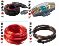
Diagrams, Schematics & Wires -- How I Done It --
***************************************************************
EDIT:
I've started a excel sheet detailing the most important details of the various DC-DC charger units as an easy to read chart.
I've attached the sheet below to download, if you have any of the missing DC-DC chargers or want to add your own . . .
download the chart edit/add in your own unit then email it back to me for uploading : [email protected]
******************

*****************
Last edited:


