[Guide] DC-DC Charger (for leisure battery) -- How I Done It --

Not DC-DC exactly . . . but it looks like this MPPT will:

reverse charge the starter battery @1A,
run lithium,
and have LTD !

*****************************

The Voltronic DUO - https://amzn.to/2Gvj3xH

upload_2020-1-26_19-16-51-png.59193


"The MPP-series controllers feature a second output so that some of the solar power can be used to trickle-charge a starter battery with a current of 1A max."


  • Nominal operating voltage: 12V DC
  • Solar module max. output: 250W
  • Solar module max. current: 15A
  • Solar module max. open circuit (OC) voltage: 50V DC
  • Max. charging current: 17.5A (aux) / 1A (starter)
  • Compatible battery types: Lead-acid (flooded, sealed), Gel, AGM, LiFePO4
  • Stand-by current consumption: 0.004 A
  • Over-charge protection: Yes
  • Reverse current protection (back drain at night): Yes
  • On-board mains suppression filter: Yes
  • Number of charging ports: 2
  • Protection against over-load, over-temperature, short-circuit: Yes
  • Connection for temperature sensor: Yes
  • Compensation for voltage loss on charging cables: Yes
  • Connection for remote display panel: Yes
  • Operating temperature range: -20 to +45°C
  • Overall dims incl. mounting flanges: 131 (W) x 40 (D) x 77 (H) mm
  • Weight: 235g
  • Manufacturer's article number: 1715
Part Number: MPP250

******************

looks like there is 4x versions goin up in charge current.


Votronic, MPPT 165 Duo Digital charge controller - https://amzn.to/2Gr4g7q

Votronic, MPPT 250 Duo Digital charge controller - https://amzn.to/2sXG6hC

Votronic, MPPT 350 Duo Digital charge controller - https://amzn.to/2t4lGnm

Votronic, MPPT 430 Duo Digital charge controller - https://amzn.to/2O1yGkP

upload_2020-1-26_19-23-45-png.59195


.

upload_2020-1-26_19-25-26-png.59197


.

*****************

https://www.votronic.de/images/Manuals/07. Solar Current Technology/1710_1715_1720_1725_e.pdf

***************

.


upload_2020-1-26_19-29-9-png.59199


.

looks like it has LTD (low temp) too . . .

upload_2020-1-26_19-32-46-png.59200


.
 
Its time to show the Renogy DC-DC (50A 25+25 if solar is involved)

Renogy 50A DC-DC On-board Battery Charger with MPPT - https://amzn.to/2QeITur

this is what you get in the box:

20200128_165958.jpg

they give you the M8 terminals which is nice =] :


20200128_170037.jpg

this is the left end:

20200128_170118.jpg

and right side :

20200128_170135.jpg

.

next job was to make up two Anderson leads to so can connect it into the van . . .

20200128_170406.jpg

Crimp on an end . . . . then heat-shrink . . .

20200128_170735.jpg 20200128_170952.jpg

now crinp on the M8 ring terminals . . . . . .

20200128_171308.jpg

this is what we end up with . . . . . 20200128_171437.jpg

Now with both sides . . . . . . and the temp sensor.

20200128_172728.jpg


you can have a look at the HS-16 crimps, cables, connectors etc over here > Kit List And Stuff -- How I Done It & What I Use --


coming up next is fitting in the van and getting some charge and performance data . . .

Coming soon . . . . . . =]


edit: Inst Man v1.0 released: https://www.renogy.com/content/RBC50D1S-G1/RBC50D1S-G1-Manual.pdf

.

upload_2020-2-11_18-28-26.png

.

upload_2020-2-11_18-29-4.png

.
 
Last edited:
Renogy RBC50D1S Pt2:

out to the van we have this . . .,
20200129_163705.jpg

i use 50A Anderson connectors so i can quickly swap kit in/out for testing and the like..

below we have a live and ground in, plus a live and ground out . . . (needed for the Victron DC-DC kit, other just use one ground)


20200129_163713.jpg

.

you can see how big the unit is here, compaited to the Redarc & Victron . . .

20200129_165717.jpg

.

20200129_165733.jpg

.
i managed to get it down by the side of the battery for testing . . .
20200129_170211.jpg

.

20200129_170219.jpg

.

after a quick test with the meter it was time to fire up . . .

to start we have the 97% Aux battery . . the DC-Dc was charging at 11.2A and the voltage was creeping up.


Screenshot_20200129-164538.jpg

.

the BMV712 readout below shows the Amps rolling off as the Volts rise . .
Screenshot_20200129-165401.jpg

..

Back over to the BM2 we see a nice steady 14.39V charge . . .

Screenshot_20200129-170331_Battery Monitor.jpg

next up will be the extended test . . .

coming soon. . . . . . . . .

Crimps, Anderson's, Cables, Fuses, chargers etc all listed here for you to see > Kit List And Stuff -- How I Done It & What I Use --
 
heres some data from the extended test . . .


this is thge start, charging at 13.74v and 11.2A
Screenshot_20200129-164538.jpg
.
this shows the steady 14.4v charge stage,
Screenshot_20200129-165705_Battery Monitor.jpg
.
this shows what happens during stop/start . . .

the charger shuts off as soon as the engine shuts down, it will then wait for the restart & >12.0v for 15 seconds before restarting the charge (which is different to most DC-DC units I've tested) . . . You can then see the initial Bulk 14.4v before dropping to 13.8v absorption.
Screenshot_20200130-050736_Battery Monitor.jpg
.

This is the BMV712 readout over 5mins with the stop/start in action,
Screenshot_20200130-103036.jpg
.

and 9mins driving with stop/start disabled.
Screenshot_20200130-104708.jpg
.

this shot shows the BM2 readyout while driving with stop/start on.
Screenshot_20200131-164208_Battery Monitor.jpg
.

the LED readouts are fairly informative . . . showing Aux battery SOC and feed power, plus alternator charging status.

20200129_165727.jpg


.

Last up we have a 24hr BM2 readout comparing both the starter and Aux batterys . . .


Starter:

Screenshot_20200204-112310_Battery Monitor.jpg

Aux:

Screenshot_20200204-112224_Battery Monitor.jpg
 
Last edited:
Want to see the proof of why you need a DC-DC (B2B) charger . . . . .

here it is . . .

doing 200mile round trip per day for work . . . . so the starter battery is fully charged daily .

here we can see the starter voltage on the right . . . . 12.5v (while cruising on the motorway)

but the Aux battery via the DC-DC charger is charging nicely @ 14.3v (Renogy DC-DC ATM)

happy days

20200220_100642.jpg


if there was a relay connecting the two batteries, no charge would be happening, and this was after 30mins of driving (during the daytime)

nighttime driving . . . (with the lights on) causes the voltage to rise slightly to 13.3v.
 
Last edited:
I thought i would do some additions today. . . .

The Aux battery is under the bench and charged via the DC-DC charger (currently a Regogy)

i decided to swap-out the Victron quick disconnect i had for the traffic light version . .

20200220_085941.jpg

its connected to the fuse block for the AUX battery . . . and allows quick connection for the Victron EHU charger (plus gives basic SOC readout)

20200220_085955.jpg

.

20200220_085725.jpg
 
The next mod for today was to add an Anderson feed (quick disconect) for an inverter - or whatever else . . .

The Andersons are good for 50A and below . . . so the 300W inverter will run off it no problems.

The rough rules is 10A per 100w drawn....ie

10A is 100w
20A is 200w
30A is 300W
50A is 500w
100A is 1000w
200A is 2000w

So this 300w inverter should draw 30A max...which is fine for the 50A Anderson plug.

500W would be the max for this style of plug...... but I wouldn't risk it..... at that power I would move over to MIDI style connection and just use 2x fuse holders as the quick disconect.

first up its bluePeter making time . . .


20200220_084940.jpg

.

i grabbed and Anderson . .

20200220_084943.jpg

some 8AWG cable, heat-shrink and some cable sock . . .

20200220_084945.jpg

.

20200220_084954.jpg
.

and with the HS-16 crimpers made up this cable (about 3ft long)

20200220_085004.jpg

.

20200220_085153.jpg

and finished off the ends with some Tesa cloth Tape . . . (plus added a end cap for safety)

20200220_085203.jpg

.


this new cable was then connected to the AUX battery fuse block via a 50A MIDI fuse . . .

20200220_084937.jpg


this fuse block lives down the side of the AUX battery . . .

20200220_084931.jpg

.


which gave us this . . . . a 50A fused anderson feed direct from the Aux battery . . .

20200220_090552.jpg

.

next up was the inverter, i cut up a Bestek 12v socket and added another adnserson plug on the end of the cable. .

20200220_091153.jpg


then just plugged the 300W pur sine inverter into that , ,. . . . like this . .

20200220_091306.jpg

at 140W via the inverter we were drawing 10.41A from the AUX battery - charging 2x Makita 18v batteries on this cheapy fake Makita charger (2x 4A outputs)


20200220_091532.jpg

..

on the monitoring side . . . we can see from the BMV712 the -11.1A being drawn from the AUX battery,

and the voltage dropping down to 12.0V due to the load . . . .


Screenshot_20200220-091625.jpg

.

Screenshot_20200220-091736.jpg

..


after 6 or so batteries were charged, i decide to start the van to see how the DC-DC charger would deal with the situation . .


we can see the 31.3A charging current (plus the 10A makita draw) so the Renogy was delivering 42A of power . .


Screenshot_20200220-141007.jpg

which steadily dropped as the AUX battery charged . . .

Screenshot_20200220-100614.jpg

.


Happy dayz . . . .

once everything settled down we were back to this . . .


20200220_100642.jpg


The van ticking over with a starter voltage of 12.5 and the DC-DC charging at 14.3 Bulk mode.

************************

after the 2hr drive home . . . . all batteries were charged and sitting at float voltages . .


..

wanna do this yourself? - - - - get stuff + ideas here >

********************************************************************

wanna do this yourself? - - - - get stuff + ideas here > Kit List And Stuff -- How I Done It & What I Use --

*********************************************************************
 
Last edited:
Great stuff.

That last image should be in a new 'guess the beer towel' competition! :):whistle:
lol . . . thats a great idea . . . . . . and i have Many, Many beer towels to try that out with . . . might make it a thing . . . . add a beer towel to every pic series.

(can you guess that one?)
 
The next mod for today was to add an Anderson feed (quick disconect) for an inverter - or whatever else . . .

The Andersons are good for 50A and below . . . so the 300W inverter will run off it no problems.

first up its bluePeter making time . . .


View attachment 61047

.

i grabbed and Anderson . .

View attachment 61048

some 8AWG cable, heat-shrink and some cable sock . . .

View attachment 61049

.

View attachment 61050
.

and with the HS-16 crimpers made up this cable (about 3ft long)

View attachment 61051

.

View attachment 61052

and finished off the ends with some Tesa cloth Tape . . . (plus added a end cap for safety)

View attachment 61053

.


this new cable was then connected to the AUX battery fuse block via a 50A MIDI fuse . . .

View attachment 61054


this fuse block lives down the side of the AUX battery . . .

View attachment 61055

.


which gave us this . . . . a 50A fused anderson feed direct from the Aux battery . . .

View attachment 61057

.

next up was the inverter, i cut up a Bestek 12v socket and added another adnserson plug on the end of the cable. .

View attachment 61059


then just plugged the 300W pur sine inverter into that , ,. . . . like this . .

View attachment 61060

at 140W via the inverter we were drawing 10.41A from the AUX battery - charging 2x Makita 18v batteries on this cheapy fake Makita charger (2x 4A outputs)


View attachment 61061

..

on the monitoring side . . . we can see from the BMV712 the -11.1A being drawn from the AUX battery,

and the voltage dropping down to 12.0V due to the load . . . .


View attachment 61062

.

View attachment 61063

..


after 6 or so batteries were charged, i decide to start the van to see how the DC-DC charger would deal with the situation . .


we can see the 31.3A charging current (plus the 10A makita draw) so the Renogy was delivering 42A of power . .


View attachment 61064

which steadily dropped as the AUX battery charged . . .

View attachment 61065

.


Happy dayz . . . .

once everything settled down we were back to this . . .


View attachment 61066


The van ticking over with a starter voltage of 12.5 and the DC-DC charging at 14.3 Bulk mode.

************************

after the 2hr drive home . . . . all batteries were charged and sitting at float voltages . .


..

wanna do this yourself? - - - - get stuff + ideas here >

********************************************************************

wanna do this yourself? - - - - get stuff + ideas here > Kit List And Stuff -- How I Done It & What I Use --

*********************************************************************
Great write up, very informative. You like the Renogy DC-DC unit then? And presumably there is no solar fitted or it’s switched off to get that 42A charge?
 
Great write up, very informative. You like the Renogy DC-DC unit then? And presumably there is no solar fitted or it’s switched off to get that 42A charge?
The Renogy is great, I love it.

And I use mobile solar, just plugged in when camping. So no solar on this occasion. That gives us upto 50A to play with
.
It's a big box ☹....
its fanless ...
Its 50A ..
It has bolt connections ..
Its takes lithium & solar..

I like it that its different from the rest... it does this odd thing where it waiting for 12 seconds before kicking in..... its charge cycles are robust..... it will even run like a VSR if you disconect the ignition feed..... it doesn't drop the output voltage to test the battery (like the redarc did)

Having said all that it's a great unit...... but I still like the Redarc best...... I've got the Redarc 1250D to test next.

But would be very happy with either the Renogy or Victron Orion or Redarc..... others I've not personally tested. Ctek, ring, sterling,
 
Nearly got my Renogy unit installed @Dellmassive and I have a question for you.
It’s a bit crowded at the terminals on the sensor side. Did you fit the Battery Voltage Sensor feed next to the IGN sensor?
My TN100 battery is going to be within 50cm of 16mm cable from the Renogy so I am not sure it’s worth fitting the BVS.
Any advice?
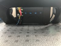
Although it’s pretty tightly packed in there it is possible to fit a Renogy/Tn100/Fusebox under a single seat with access although there is only 2mm clearance under the RIB swivel and I have the heated seats cable to squeeze in.
upload_2020-4-7_19-0-56.jpeg
Obvious where the battery goes. VW wiring altered to fit. Towbar loom rejigged to fit at the back with the fuse box giving access to the OEM fuses from the rear of the seat.
upload_2020-4-7_19-9-5.jpeg
Access to the Renogy at the front for checking functions.
 
Last edited:
Nearly got my Renogy unit installed @Dellmassive and I have a question for you.
It’s a bit crowded at the terminals on the sensor side. Did you fit the Battery Voltage Sensor feed next to the IGN sensor?
My TN100 battery is going to be within 50cm of 16mm cable from the Renogy so I am not sure it’s worth fitting the BVS.
Any advice?
Although it’s pretty tightly packed in there it is possible to fit a Renogy/Tn100/Fusebox under a single seat with access although there is only 2mm clearance under the RIB swivel and I have the heated seats cable to squeeze in.
View attachment 65313
Obvious where the battery goes. VW wiring altered to fit. Towbar loom rejigged to fit at the back with the fuse box giving access to the OEM fuses from the rear of the seat.
View attachment 65316
Access to the Renogy at the front for checking functions.
Looking good . . . .

To answer the question : "did I fit the Battery Voltage Sensor feed next to the IGN sensor?" - no i didn't, because same as you i fitted the unit right next to the Leisure battery. So there is next to no volt drop from the dc-dc to the battery.

If the dc-dc was remote from the leisure battery then yes i would fit that feed.. (ie If the dc-dc was up front in an engine bay and the leisure battery was at the rear of the van or in a towed caravan.
Thanks for that, pretty much what I thought. I wired it to the unit but will take it out again as there’s not much space and it’s one less pair of ring terminals at the back.
If a jobs worth doing it’s worth taking bloody ages to finish:whistle:
 
It’s all in and working fine, big thanks for all the advice direct and from your reviews @Dellmassive made things a lot easier for me. The Renogy/TN100 seem to be working fine together but no solar fitted yet.
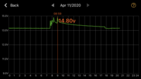
This is the days TN100 voltage trace, not much to show. 5 short trips this morning to shops and deliveries. The first three were really short. To and from Sainsbury’s is the longer peaks. Then it sat on the drive doing nothing until 17:45 when I fired up the Planar heater for 40 minutes testing the remote app function.
1586633391399.png
 
Back
Top