Now what is needed is a mini duct to blow air over the resistor once the blower is operated to keep it cool.
You are using an out of date browser. It may not display this or other websites correctly.
You should upgrade or use an alternative browser.
You should upgrade or use an alternative browser.
Heater only working at maximum
- Thread starter HHO
- Start date
-
- Tags
- 7e0959263d heater
Now what is needed is a mini duct to blow air over the resistor once the blower is operated to keep it cool.
The resistor pack sits in the main blower air flow duct for cooling. I have suspected the problem is the resistor pack getting too hot on speed 1 - so less air flow. Mine have always failed when on speed position 1.
Of course it could be due to a faulty blower motor drawing too much current causing the resistor pack to overheat. This is where the thermal fuse is designed to do its job.
All I know is my blower motor appears to work OK and no immediate failures when a new resistor pack or thermal fuse is fitted.
I should have said the over the thermal fuse rather than resistor. Brain is out of gear! There must be a safe fix for this fault rather than keep throwing new resistor packs or thermal fuses at the problem.
Was it the lack of a thermal fuse the cause of those vehicles that kept bursting into flames?
If it is the position 1 that causes it my solution would be to disconnect that speed if at all possible without causing a further problem. My thinking is that position 1 is such a low airflow it would not be missed much.
Mine was always left in position 2!!! Let's see how long these last me... Car Heater Motor Resistor Thermal Fuse Repair Link Audi VW Skoda 5 PCS | eBay
That's my theory out of the window then!
I'd say it is only speed/stage 3 that can blow the fuse. As above the current to the blower travels through the fuse only at switch positions 1-3.That looks like the one @Pauly , 4pin including thermal cut-out.
N24 - Fresh air blower series resistor with overheating fuse
fed from -
J301 - Air conditioning system control unit
restive load for blower motor stage 1,2,3 and direct feed for stage 4.
.
View attachment 32760
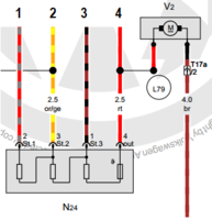
A measurement of current draw of the blower. Obviously there is some variation depending on voltage, air density (cold air=more dense), blockages on airway exits, etc. Most likely did the measurements engine off, so they could be a bit higher engine running. Obviously need to have another session...

Stage 1 = 3.3 A;
Stage 2 = 5.4 A;
Stage 3 = 10.2 A;
Stage 4 = 18.9 A.
EDIT: picture manipulation
Last edited:
But we are not worried about the current here surely? It is a thermal fuse and the resistor will get hottest on position 1. Taking the temperature at the various speeds would be more informative.
In this configuration speed is controlled by reducing air blower motor supply voltage.
Speed adjustment is divided in 4 stages, obviously disregarding no supply voltage (Stage 0).
When Stage 4 is selected(max motor speed) full supply voltage is directly connected to the motor and overheating fuse is effectively bypassed.
If Stages 1, 2 & 3 are selected motor speed is reduced accordingly and supply voltage is connected via corresponding resistor/resistors and overheating fuse.
As the overheating fuse reacts to excessive temperature and not to excessive current I am convinced that this problem is down to the quality of the fuse itself.
Unless there is a problem with the air blower motor and then excessive current would be sufficient to cause the thermal fuse itself to heat up to the trigger temperature.
You may well be on to something with the quality of the thermal fuse - after I replaced my shower fan one with one with the same value I have had no further fuse blows.
What worries me is the number of replacement resistor packs that are offered for sale for all varieties of vehicles, does this mean that this means of varying motor speed is not up to the task generally?
( When you see the old Webasto glow plug resistor you can see the lengths to which they went to ensure good heat dissipation, open coil of resistance wire on a ceramic core on a heavy steel enclosure that had to be affixed to steel heat sink piece of bodywork):
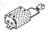

It is typical manufacturer's approach these days across all industries to design equipment not to last. Another words to fail after reasonable amount of time and to force consumers to buy replacement components. Also component replacement setup/procedures are designed to maximise consumers expense and therefore maximise manufacturer's profit. Rip off across the board 
Here is the T3 solution to the problem - VW Electrics Dash Fan Control Upgrade - VW T25(T3)-Tech using a PWM motor controller instead of the resistor. Here it is a mixture of the resistor melts surrounding plastic and the switch contacts burning out. As to whether something like that would be suitable for integrating with the T6 electrical system I don't know, I suppose it would need to be part of the design right from the start.
As to whether something like that would be suitable for integrating with the T6 electrical system I don't know, I suppose it would need to be part of the design right from the start.
Could be done as a plug and play solution quite easily. VW won't as @Robert has said due to cost.
PMW (pulse width modulation) is really a bit of an overkill for a non-ctitical motor speed though. But it would be more efficient.
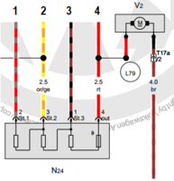
Measured front blower current (engine off):
Stage 1 = 3.3 A;
Stage 2 = 5.4 A;
Stage 3 = 10.2 A;
Stage 4 = 18.9 A
At 20 °C the resistor values are:
R(St1) = 1.24 ohm
R(St2) = 0.82 ohm
R(St3) = 0.38 ohm
Blower (off) = 0.50 ohm
Thermal fuse has identifier 192KR1.Power dissipation (P = I²R) at different stages would thus be:
Stage 1 = (3.3A)² x 2.44 ohm = 27 W
Stage 2 = (5.4A)² x 1.20 ohm = 35 W
Stage 3 = (10.2A)² x 0.38 ohm = 40 W
However, the resistors seem to be PTC resistors and cooled by airflow thus a bit more evaluation is needed...
Taking the temperature at the various speeds would be more informative.
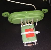
Fortunately I have another blower in load area where access is easy so it may serve now as test platform.
EDIT: part number 7E0959263D (for both front and rear blowers)
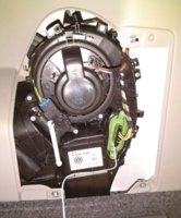
Last edited:
It was another school day  Such a simple device - a blower series resistor for regulating fan speed - been in use for decades...
Turned out to be a multidimensional challenge - electrical efficiency, heat conductivity, fuse cooled by airflow, heat transfer function, etc.
Anyways, thanks again for the inspriration to the members of the Forum, now especially:
Test setup to emulate front heater fresh air blower:
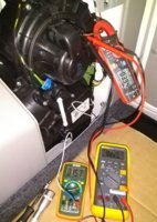
The protocol:
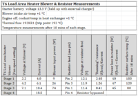
Note: This is not the temperature at thermal fuse - just on resistor surface having a sensor glued there and covered by a foam patch. Would be another challenge to pick it up on/in the fuse. Just wanted to clarify to myself what's going on in the neighbourhood.
Actual wiring diagram used in the test- same principle and pinouts as for front blower (shown earlier in the thread).
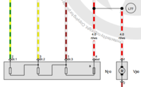
However, under slightly different conditions... pushing up battery voltage, intake air temperature... reaching already 210 °C

Turned out to be a multidimensional challenge - electrical efficiency, heat conductivity, fuse cooled by airflow, heat transfer function, etc.
Anyways, thanks again for the inspriration to the members of the Forum, now especially:
The resistor pack sits in the main blower air flow duct for cooling. I have suspected the problem is the resistor pack getting too hot on speed 1 - so less air flow. Mine have always failed when on speed position 1.
But we are not worried about the current here surely? It is a thermal fuse and the resistor will get hottest on position 1. Taking the temperature at the various speeds would be more informative.
As the overheating fuse reacts to excessive temperature and not to excessive current I am convinced that this problem is down to the quality of the fuse itself.
Mine was always left in position 2!!! Let's see how long these last me..
My wife’s Ford Fiesta blows the resistor pack about once a year. It’s a common theme on various cars
Seems to be becoming a bit of a common issue this one,
That looks like the one @Pauly , 4pin including thermal cut-out.
N24 - Fresh air blower series resistor with overheating fuse
fed from -
J301 - Air conditioning system control unit
restive load for blower motor stage 1,2,3 and direct feed for stage 4.
View attachment 32760
The thermal fuse may be the symptom rather than the cause, it could be there's a design fault in the resistor pack, or the blower, or the positioning of the fuse, that's causing the overheating. Like you say, it's a shame they don't give a toss and just swap it out instead of identifying the issue and modifying the part - it's been an issue for over 10yrs and carried over from the T5.
Test setup to emulate front heater fresh air blower:

The protocol:

Note: This is not the temperature at thermal fuse - just on resistor surface having a sensor glued there and covered by a foam patch. Would be another challenge to pick it up on/in the fuse. Just wanted to clarify to myself what's going on in the neighbourhood.
Actual wiring diagram used in the test- same principle and pinouts as for front blower (shown earlier in the thread).

However, under slightly different conditions... pushing up battery voltage, intake air temperature... reaching already 210 °C


Last edited:
Excellent work there @mmi 


Interesting the resistor surface temperature on speed 1 is 180 deg. As expected - maximum voltage drop, maximum dissipation. It would not take much to increase the dissipation; i.e. Increased input voltage or higher current draw by a cold motor with stiffer bearings/bushes, and then you could get to 192 deg fuse level. The fan motor could be running slower so less air flow too over the resister pack and fuse.


Interesting the resistor surface temperature on speed 1 is 180 deg. As expected - maximum voltage drop, maximum dissipation. It would not take much to increase the dissipation; i.e. Increased input voltage or higher current draw by a cold motor with stiffer bearings/bushes, and then you could get to 192 deg fuse level. The fan motor could be running slower so less air flow too over the resister pack and fuse.
Similar threads
- Replies
- 9
- Views
- 1K
- Replies
- 4
- Views
- 627
- Replies
- 8
- Views
- 1K
- Replies
- 8
- Views
- 2K
- Replies
- 1
- Views
- 900
