Hillside Birchover

Started my upgrade to Lithium on my 2023 Birchover Classic yesterday, which I will show progress on in this thread, as and when.

This morning I found some “interesting“ wiring from Hillside under the passenger seat.
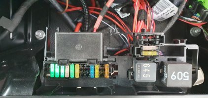
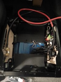
They’ve “spliced” into the engine run signal from the BCM to the battery isolation relay with a 0.5mm2 grey wire which they have then fused at 40A before it heads off, again in grey 0.5mm2, to a relay in the back cupboard; buzzing out it seems to be something to do with the water pump as a yellow wire on the same relay goes to the tap pump switch. Nothing on their supplied wiring diagram matches such wiring.
Working out the purpose is for another day, when the van isn’t so stripped out, can’t turn ignition on, but immediate issues are;
Who in their right mind fuses a 0.5mm2 wire at 40A, which is way beyond the current handling capacity of the wire? Will be changing that to a 10A.
Where was the person trained to do a ”splice”? They’ve basically stripped the insulation over a 40mm length of OEM wiring, wrapped their wire round it and then liberally applied solder, before covering it in fabric tape. Needless to say the OEM wire broke off at the end when I was uncovering it. Certainly wasn’t how I was trained.
Picture (not the best) for amusement.
So much for Hillside saying they don’t touch the OEM wiring and what a poor job.

View attachment 216686
Just run that whole “Type Approval “ thing by me again :whistle:
 
Just run that whole “Type Approval “ thing by me again :whistle:
Incorrectly rated fuse shouldn’t happen and neither should poor wiring practices or incorrect documentation.
Mine may be an isolated example and its going to be sorted by the time I’m finished.
As I said before, I don’t feel I paid a premium for any Type Approval, certainly compared to other conversions and similar issues could and probably do occur with them too.
 
I have always suspected that Manufacturer "Type Approval" has absolutely nothing to do with the 'camper-side' conversion and everything to do with whether the conversion compromises the base vehicle.

Although @EAN 's experiences would suggest otherwise;)
I understand there are TWO type approvals that apply to a Hillside converted vehicle. The first is the VW European Community Whole Vehicle type approval to show that every Transporter sold in the EU and UK meets mandatory environmental, safety and security standards. Each vehicle has a plate attached to show this.

The second type approval that Hiilside has specifically for their conversions relates to the modifications made to a vehicle adapted as a ‘special purpose vehicle’ of Category M adapted or constructed for passenger-carrying and or to include accommodation space containing a minimum of specified equipment. In this case, such modications (for are certified by the UK Vehicle Certification Agency against mandatory requirements. A second plate affixed to the vehicle shows this second approval.

This probably accounts for why Hillside along with Jerba, Bilbos, Rolling Homes, CMC, etc are somewhat conservative in terms of their design specification and often won’t agree to certain types of customer modification requests as it would mean the vehicle would have to be re-certified, not doubt at significant cost.
 
  • Like
Reactions: CAB
I think there are TWO type approvals that will apply to a Hillside converted vehicle. The first is the VW European Community Whole Vehicle type approval to show that every Transporter sold in the EU and UK meets mandatory environmental, safety and security standards. Each vehicle has a plate attached to show this.

The second type approval that Hiilside has for their conversions relates to the modifications made to a vehicle adapted as a ‘special purpose vehicle’ of Category M adapted or constructed for passenger-carrying and or to include accommodation space containing a minimum of specified equipment. In this case, such modications are certified by the UK Vehicle Certification Agency against mandatory requirements. A second plate affixed to the vehicle shows this second approval.

This probably accounts for why Hillside along with Jerba, Bilbos, Rolling Homes, CMC, etc are somewhat conservative in terms of their design specification and often won’t agree to certain types of customer modification requests as it would mean the vehicle would have to be re-certified, not doubt at significant cost.
Do you have a picture of the second plate as my Birchover doesn't have one? Maybe I need to ask Hillside why not or if it was missed?
 
Do you have a picture of the second plate as my Birchover doesn't have one? Maybe I need to ask Hillside why not or if it was missed?
It’s usually on the drivers door B pillar below the lock catch and next to the tyre pressure label. According to a note I made, it shows Hillside’s address and gives the Type Approval number ( “g11*2007/46*00346* Stage 2“). It also gives the vehicle’s factory VIN. I’m away so not near the van to take a picture just now.
 
It’s usually on the drivers door B pillar below the lock catch and next to the tyre pressure label. According to a note I made, it shows Hillside’s address and gives the Type Approval number ( “g11*2007/46*00346* Stage 2“). It also gives the vehicle’s factory VIN. I’m away so not near the van to take a picture just now.
I speak to Hillside about it next week:)
 
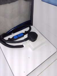
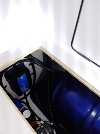
Finally finished replacing my CBE CB516-3 16A mains charger with a Victron Blue Smart IP65 12V 15A mains charger so that I have a lithium charge profile on EHU.
I disconnected all power sources (my leisure battery install is currently stripped out), removed the cover (2 screws) from the CB516 and disconnected both the mains input connector and the dc output connector.
Then I undid the 4 screws and removed the CB516 from the hinged side.
Tracing the original dc cable back towards the rear cupboard, the cable is joined via two 6.3mm spade terminals about midway along the bottom of the hinged access panel; this is where the CB516 wiring joins the Hillside loom. The connections are covered in PVC tape and then cloth tape which I removed so that I could connect the Victron at this location as it was convenient and the wiring also increases in CSA at this point: I chose to keep the original Victron quick connector and mounted it to the hinged access panel. Using an accessory cable, I cut off the ring eyelets and crimped on a couple of insulated spade terminals, connected it to the Hillside loom and secured with PVC tape and cloth tape as per the original wiring.
Next I cut off the mains connector from the original CB516 feed, fitted a single socket with 20mm conduit entry onto the hinged access panel and rewired the mains cable to the socket, securing with a cable gland.
I then secured the Victron charger to the side of the cupboard in the wheel arch void and fed both cables up to the hinged access panel. Covered all the wiring in split conduit and secured with a mixture of p clips and cable ties. Job done.
Only all the rest of the lithium install to do now.

IMG_20231019_115508_183.jpegIMG_20231019_132821_805.jpeg
 
Started my upgrade to Lithium on my 2023 Birchover Classic yesterday, which I will show progress on in this thread, as and when.

This morning I found some “interesting“ wiring from Hillside under the passenger seat.
They’ve “spliced” into the engine run signal from the BCM to the battery isolation relay with a 0.5mm2 grey wire which they have then fused at 40A before it heads off, again in grey 0.5mm2, to a relay in the back cupboard; buzzing out it seems to be something to do with the water pump as a yellow wire on the same relay goes to the tap pump switch. Nothing on their supplied wiring diagram matches such wiring.
Working out the purpose is for another day, when the van isn’t so stripped out, can’t turn ignition on, but immediate issues are;
Who in their right mind fuses a 0.5mm2 wire at 40A, which is way beyond the current handling capacity of the wire? Will be changing that to a 10A.
Where was the person trained to do a ”splice”? They’ve basically stripped the insulation over a 40mm length of OEM wiring, wrapped their wire round it and then liberally applied solder, before covering it in fabric tape. Needless to say the OEM wire broke off at the end when I was uncovering it. Certainly wasn’t how I was trained.
Picture (not the best) for amusement.
So much for Hillside saying they don’t touch the OEM wiring and what a poor job.
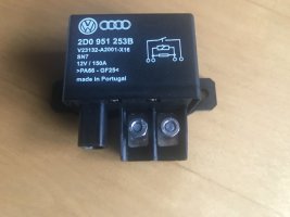
When you were delving into your Birchover did you happen to come across a component labelled ‘Amber Valley Smart Charger’ linked to the leisure/auxiliary battery in the habitation area? I was looking at the circuit diagram in my Hillside manual (for my 2023 Birchover) and noticed it showed one of these connected to the leisure battery. It looks like it’s a split charge relay but I suspect that the diagram is out of date and it’s actually got a VW factory fitted relay that functions as a split charge relay.

The reason I ask is that I’m planning to replace the relay with a DC-DC + MPPT charger at some point (either a CTEK D250SE or a Redarc BCDC 1225D) and want to understand Hillside’s electrical architecture before I kick things off.
@Captain Quick You suspect correctly; there is no ‘Amber Valley Smart Charger’. Standard VW split charge relay is fitted.
Hope the splice that Hillside put in for the Engine Run signal is better done on yours than it was on mine and also that it isn’t fused at 40A like mine was!!
I’m currently right in the middle of fitting a REDARC BCDC1240D.
I haven’t unwrapped the insulation around the splices yet so I don’t really know what to expect but on the basis of your experience I’m not as positive as I’d hope to be. Just now, I’ve parked things until next spring when I’ll fit the DC-DC /MPPT charger and a solar panel. For the time being though, I’m just going to add a connector under the passenger seat to hook up a CTEK conditioner to keep the starter battery charged once I’ve decided on the best place to pick up the +ve connection.

Right now, I’m trying to understand the Birchover underseat wiring topography as much as I can so I can map it to the VW and Hillside circuit diagrams. Sadly, neither appear to be clear, well-documented or particularly accurate. Any pictures of your underseat wiring (before, during and after modification) you would be willing to share would therefore be very much appreciated.

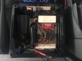
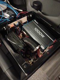
FYI, my passenger seat wiring looks like this…

IMG_2008.jpeg
 
I haven’t unwrapped the insulation around the splices yet so I don’t really know what to expect but on the basis of your experience I’m not as positive as I’d hope to be. Just now, I’ve parked things until next spring when I’ll fit the DC-DC /MPPT charger and a solar panel. For the time being though, I’m just going to add a connector under the passenger seat to hook up a CTEK conditioner to keep the starter battery charged once I’ve decided on the best place to pick up the +ve connection.

Right now, I’m trying to understand the Birchover underseat wiring topography as much as I can so I can map it to the VW and Hillside circuit diagrams. Sadly, neither appear to be clear, well-documented or particularly accurate. Any pictures of your underseat wiring (before, during and after modification) you would be willing to share would therefore be very much appreciated.

FYI, my passenger seat wiring looks like this…

View attachment 218259
@Captain Quick Looking at your pic, it looks like you have 3 aftermarket fuses in the row of 12 (right side of your pic): The 40A will be the fuse for the main wire going back to the Hillside rear cupboard leisure fuse box. The 15A and 20A, if like mine, route together and exit through the bottom of the vehicle under the drivers seat: My current assumption is that they are for the diesel heater (wiring not documented on Hillside’s circuit at all) but I won’t get to clarify until I’m ready to power back up.
You don‘t have the second (incorrect 40A) fuse that I had, which on mine was fitted in the left most position on your pic, but there will be a fuse in the block of 12 which will have two aftermarket grey wires for the feed and return (This is the engine run signal that will be spliced from the split charge relay and fed back to the rear cupboard). You have more factory VW fuses than me by quite a margin. I can’t remember off the top of my head how many of the 12 fuses are fed by a common bus bar at from the leisure battery, but I’ll check and post a pic later.
I had a spare 10mm2 12V starter feed taped off under the passenger seat. It also had a smaller wire attached that went into the 12 way fuse block, which only fed empty locations on mine. If you have this wire it would be the easiest point to fit your conditioner.
There’s also a GND stud under the middle of the passenger seat that you can connect to.

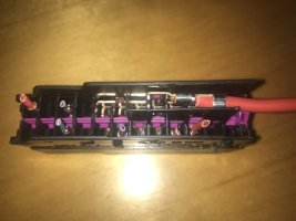
Edit: 8 fuses are fed by a common bus bar. In my photo you can see the bus bar.IMG_0869.jpeg
 
Last edited:
@Captain Quick
The split charge relay has 6mm dimeter connections. Probably the absolute easiest way to get your conditioner wired in before you do something more permanent would be to make a short length cable using 6mm diameter battery connectors, then using a 6mm power post you could disconnect the starter battery feed to the split charge relay and connect it to the power post. Connect your short cable between the power post and the split charge relay and now you have a positive connection that you can add in your conditioner: Insulate the power post in an enclosure or by some other means and you’re sorted and it’s totally reversible.IMG_0872.jpeg
 
@Captain Quick
The split charge relay has 6mm dimeter connections. Probably the absolute easiest way to get your conditioner wired in before you do something more permanent would be to make a short length cable using 6mm diameter battery connectors, then using a 6mm power post you could disconnect the starter battery feed to the split charge relay and connect it to the power post. Connect your short cable between the power post and the split charge relay and now you have a positive connection that you can add in your conditioner: Insulate the power post in an enclosure or by some other means and you’re sorted and it’s totally reversible.View attachment 218262

@EAN Many thanks for the very helpful input.

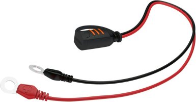
If I understand the wiring configuration correctly, I think I should be able to connect a CTEK connector (like this one in the picture below) with the +ve (red wire) eyelet onto the starter battery post on the split charge relay and the -ve (black wire) eyelet onto the the chassis post on the floor. I think that should allow me to attach the CTEK conditioner to keep the starter battery charged as and when I need to.


.IMG_2010.jpeg
 
Last edited:
@EAN Many thanks for the very helpful input.

If I understand the wiring configuration correctly, I think I should be able to connect a CTEK connector (like this one in the picture below) with the +ve (red wire) eyelet onto the starter battery post on the split charge relay and the -ve (black wire) eyelet onto the the chassis post on the floor. I think that should allow me to attach the CTEK conditioner to keep the starter battery charged as and when I need to.


.
@Captain Quick Yes exactly, I added the extra power post and short cable as I’m not sure you would be able to get a second +ve wire onto the split charge relay starter battery terminal stud.
Also If you don’t want to disturb the chassis post under the floor you could connect your -ve lead to the -ve of the leisure battery as it connects straight to it anyway.
I‘ve added a charger quick connection to my (in progress) wiring and topped the starter battery up the other day as I can’t use the van.
 
Back
Top