Too Many OBDii Faults For My Liking!

Almost, edit the last bit to Starter/Solar then Leisure.
DOH :sick:

Basically the DC/DC charger needs somewhere to output its current to (a bucket if you like)
If you were to connect the solar input (hosepipe in) before the leisure battery the DC/DC charger would be trying to pass the charge through but have nowhere to put it (water everywhere) and I have heard somebody damaged their charger because of this.
It is not explicit in the manual, but there is a warning led that comes on if connection to leisure battery is not there when an input is connected, it doesn’t warn what might happen if you don’t sort it out and disconnect the input asap so it doesn’t get a chance to break anything.
Now it makes complete sense. Sorry you had to explain in numpty terms :oops:
Can you see this LED in the position you have installed your unit? Wonder if it could be extended or replaced with a buzzer?! Although I’m sure this is OTT as I will probably do it the old fashioned way and hang a warning label on it.

Just leave the blue wire disconnected (pull the fuse out) until you have the smart alternator fixed. It will work like it would if you didn’t have a smart alternator until then.
I thought that would make sense and what you might recommend.
 
Use a normal LED connected to the green wire to extend the front panel LED (Page 5 of the manual & diagram on page 11)
 
I thought/think that was for use with lithium only but tell me if I'm wrong. I'm using power frame lead acid
 
Call me Mr thicky but I still don't get it :(

I was originally under the impression the orange cable gets left disconnected but not sure any more!

Your 1.3.3 is different to the one on my operators manual, see attached

EDIT: I've been meaning to mention I don't have solar as of yet so presumably will just leave the yellow wire disconnected for now?
 

Attachments

  • redarc-bcdc-dual-input-instruction-manual.pdf
    599.2 KB · Views: 4
That’s right, right at the top of my last post..
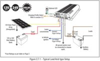
Lead Acid is Profile A (Orange wire left disconnected) max voltage is 14.6V.
Picture is the same though. Figure 2.7.1 is Lead Acid set up, 2.7.2 is LiFePo4
I took my screenshots off the manual I downloaded from Redarc’s website just before I took the S/S’s, it is different and bottom of page 1 it says version 6 where yours says version 2.
https://www.redarc.com.au/Content/Images/uploaded/Manuals/BCDC Dual Input Instruction Manual.pdf
No solar? Leave the yellow disconnected and isolated yes.
 
Thanks once again.

And just in case it's helpful for others I have now compared the two documents REV2/REV6 and can confirm it is only the optional external LED section (1.3.3) which has been added, moving charging process to 1.3.4.
 
Hello Grim Reaper

I have my set-up connected back together and back over to the van again shortly to do some more as the van is still being stored at my sons place.

Last night I got the Redarc connected temporarily but I'm wondering if I have it working correctly. Currently the profile LED seems to just flash continuously every second but I have checked the troubleshooting part of the instructions (attached) but can't see anything I have done wrong.

Currently my leisure batteries at rest are 12.96 volts and I wasn't sure I'm reading the instructions right and whether this means they won't charge, I'm also not sure of the current voltage of my starter battery and the role it plays in when the Redarc is switched on.

Bizarrely at one time I had the engine off but ignition on and temporarily the profile light was on solid and the vehicle and stage lights too. Unfortunately I had to leave shortly after this so didn't get to try it again.

Redarc.png .
 
12.9V should be fine, there is mention of 4.2V in that clip but that would suggest the battery is REALLY dead.
Just go through everything and check voltages and connections.
12V positive from starter battery (fuse in place?) getting to the red wire into the Redarc.
Black Ground wire connected to vehicle ground/ and/or both Starter and Leisure batteries connected to same. (I used double core red & black cable from both starter battery and leisure battery to under passenger seat and commoned the ground wires on a busbar with a further connection to ground under the seat)
Brown wire to leisure battery (via fuse again) 12v on there.
Blue wire going to your ignition switched live, check it goes live when ignition is on.
Orange wire- as determined by your leisure battery type.
The selected profile led will be on solid when the unit is ON and CHARGING, a flashing profile led indicates the unit is in STANDBY mode and NOT CHARGING.
 
There is a youtube vid that shows how to connect up, he drones on a bit but the part I took away from this was around 4:55 onwards, they mention connecting grounds first, then leisure battery then starter battery.
 
Thanks!
12.9V should be fine, there is mention of 4.2V in that clip but that would suggest the battery is REALLY dead.
Just go through everything and check voltages and connections.
12V positive from starter battery (fuse in place?) getting to the red wire into the Redarc.
Checked
Black Ground wire connected to vehicle ground/ and/or both Starter and Leisure batteries connected to same. (I used double core red & black cable from both starter battery and leisure battery to under passenger seat and commoned the ground wires on a busbar with a further connection to ground under the seat)
Checked and did exactly the same
Brown wire to leisure battery (via fuse again) 12v on there.
Checked
Blue wire going to your ignition switched live, check it goes live when ignition is on.
Not using yet, if you recal I have the possible alternator issue meaning I've left disconnected for now. I get 14.18V the engine running.
Orange wire- as determined by your leisure battery type.
Checked set for lead acid
The selected profile led will be on solid when the unit is ON and CHARGING, a flashing profile led indicates the unit is in STANDBY mode and NOT CHARGING.
Strangely I found the video you posted earlier and had left it on my laptop to watch later!

The only other thing I can think might be worth checking is as per attachment below

Redarc_Stuck.png
 
I've watched it and notice on the video the chap says connect orange to common ground for lead acid yet the instruction pdf I have (presumably the same as yours now - REV6) says leave disconnected!
 
The recent manual only gives max voltages not types of battery, so needs some data from the battery manufacturer to set it correctly.
 
Yes I realise that but may not have explained every well :oops:

I have lead acid batteries and they instruct don't charge over 14.8 volts absolute maximum, so Profile A was always going to be my only option. The manual says leave the orange un-connected but the video contradicts this by saying connect to ground!
 
I saw on one of the redarc forums that somebody was only getting a low voltage out of the setting that should have been correct for his battery so he was advised to up the output to the next level and this gave a better output voltage, check with a meter once you have everything in and charging.

Sorry, read that wrong, here is the post..
Hi Joshua,
Thank you for your post.
On the standard setting you should see a maximum charging voltage of 15.0 volts. The 13.3 volts you have read may have been the float mode voltage.
If your maximum charging voltage is 14.8 volts then I suggest to use the AGM setting, this will still charge your battery to 100%

Regards
Cameron
 
Last edited:
The manual says leave the orange un-connected but the video contradicts this by saying connect to ground!
This is why they changed the labelling from AGM/Lead-Acid/Calcium to ABC and gave voltages.
It would seem that as battery manufacturers changed their charging requirements the labelling was misleading some and overcharging was occuring.
If the battery you have says max 14.8, go with the AGM option (14.6) Option A and leave the orange wire isolated.
 
Errrrmmm this is an embracing one :oops::oops::oops:

I can't believe I managed it but I had the input (from starter battery) and output (to leisure batteries) arounds the wrong way. The only excuse I can make is that due to the tightness on my sons drive I was working overhand to the front of the seats so my head under the dash and backside in the back of the van.

Hopefully it didn't break anything but currently on starting I have 14.33v coming to the leisure batteries from the Redarc :D

Debt of gratitude to you Grim Reaper as wouldn't of got there without all your help.

Now that just leaves connection to the fridge and battery monitor then time to put the seats back in me hopes.
 
I can't see any other way to test the connection between alternator and the Battery Monitor. Actually I would trust the VCDS on this, as it couldn't command the alternator, there is a disconnect. It is obvious that 61-Battery Monitor (at battery) communicates with BCM - that's where the other end of the LIN bus goes - as this works it means there is can't be short to ground on the bus.
Agreed. It's even more challenging as the BCM is on the same bus.
Actually, (as I believe there is a break on the bus) I would prepare a wire which I could connect from yellow/green at battery terminal to yellow/green at alternator plug (thus in parallel to original wiring). And then use VCDS to run the output tests again - to see if they pass then.


or disconnect plugs on the same bus and see if readings change.
You might get a reading that looks like voltage if you back probed the plug at the battery shunt with a digital meter, it would be meaningless though as all you are seeing is a square wave data stream pulsing which makes it appear to be a fluctuating voltage, but it would give an indication of continuity at least.
see if you get a similar reading with the plug disconnected, both on the plug and on the socket (even better if you could only take the green yellow wire out of the plug to test)
Have a watch of DiagnoseDan on you tube for some great diagnostic instructional videos on what can go wrong with canbus networks.
Hello chaps,

Pleased to say my electrics are complete and seem from the initial short tests I have had time for to be working great. Thanks for all the help on here :thumbsup:

Now back onto this coding issue that may or may not be caused by the cable to the negative shunt.

I have tested again today and get like first attachment
If I unplug the cable from the shunt I get Like second
And the third if I unplug the cable from the shunt and additionally follow the same as Loz does at the top of the thread here (Override Start Stop System).
 

Attachments

  • Negative shunt plugged in and stop:start at -50 deg.txt
    8.1 KB · Views: 7
  • Negative shunt unplugged and stop:start at -50 deg.txt
    8.1 KB · Views: 5
  • Negative shunt unplugged and stop:start at 1 deg.txt
    8.4 KB · Views: 7
I have tested again today and get like first attachment
If I unplug the cable from the shunt I get Like second
And the third if I unplug the cable from the shunt and additionally follow the same as Loz does at the top of the thread here
If I read these correctly - you cleared the fault(s) before each scan (as the fault time stamp is always new).
The engine was not running? As I would have expected see eventually the fault registered by the engine too.
Here you can find some related bedtime stories ► Transporter 2010-2015
 
Back
Top