Hi everyone,
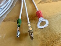
could I get a bit of guidance on the wiring please? The T91 and receiver hasn't turned up yet but I have the wiring kit now which has 3 wires: earth (I can figure that one out), permanent + (do I need to connect this to the red plug under passenger seat?) and one wire labeled 'pin 6' (the one with green sleeve in photo, again is this for the red plug?).

Also there are two red plugs under the seat - which one is it?

I have ODIS now but not managed to get it connected to the van yet. Feel another challenge coming up with that.

Cheers

Stefan

IMG_4311.jpg

IMG_4302 2.jpg
 
It's the red connector (T17p) which has 17 pins. See the wiring in -

You could take permanent +12V e.g. from pin 17 (red/yellow wire). See the attachment of
 
Hi there, have a look here

Not sure what year your van is but the diagrams are for 2019 ~ 2020


Thanks it's a 2016. I'll see if I can figure it out. I'm not that great with wiring diagrams.
Where would I connect to the LIN Bus, is that pin 6 in the same red plug?
 
@stoem Unfortunately the diagrams I linked to are T6.1

Looking at the actual terminals on the end of each wire they are both different.

This is the pinout of the connector and I would expect the pin 6 hole to be empty.
17p.png
Do the instructions you have say the wire with green grommet is Lin bus?
That looks like it will fit position 6 in plug.

The other wire looks like it will only fit position 15 or 17 in the same plug.

I would say the plug in your picture is the top one. the other looks darker, brownish?

Just remember, once inserted in the plug the terminals can be removed but you need a special tool to press the release prongs flat.

I would test the other pins, 15 or 17 with volt meter first to see if they are permanent live, assuming they don't have a wire in already.
Also you might have to fit a fuse in nearby fuse holder to supply power.
Unfortunately the relevant wiring diagram is not listed in the downloads section yet.

Double check before inserting the terminals!
 
Thanks it's a 2016. I'll see if I can figure it out. I'm not that great with wiring diagrams.
Where would I connect to the LIN Bus, is that pin 6 in the same red plug?
The wiring diagram below or here in section 59.
It is just power and LIN Bus - to pin 1 of the red 17-pin plug. There should be mating green/white wire.
 
If you go to cardiagn web site
The wiring diagram below or here in section 59.
and look at wiring diagram for Transporter 2016 >, page 1396 shows fuse box under left seat.

I might look to put the permanent live wire into there, No. 8, 14 and a few others are not used.
 
Thanks everyone, the T91 kit is being delivered today so I should have everything ready shortly. I'll investigate with voltmeter etc and report back.
 
I have managed to start the aux heater with Webasto multicontrol car (second hand that was already installed on a T5 it has 3 wire + ; - ; signal
 
Thanks again. My first step was to check heater model I have installed before attempting to flash the firmware but I am having problems with ODIS-S which I have never used before. It was tricky to install but seems to work (up to a point).

I've posted details in another thread if anyone has any advice?
Advice needed on ODIS-E

Thanks.
 
@stoem Unfortunately the diagrams I linked to are T6.1

Looking at the actual terminals on the end of each wire they are both different.

This is the pinout of the connector and I would expect the pin 6 hole to be empty.

Do the instructions you have say the wire with green grommet is Lin bus?
That looks like it will fit position 6 in plug.

Thank you. There are no specific instructions with my kit but I've found a PDF some from another company that sells an upgrade kit which specifies that the signal wire should connect to a green/white wire on the same connector block under the seat.

T6_Webasto_1.jpg
 
Ok I made some further progress but need some more guidance please.

I've got ODIS running and was able to read the identification data for the aux heater of my T6 Caravelle 2016 (Climatronic)

Control module J364
Software part no 7E0 963 273 A
Software version 9
Hardware part no 7E0 963 273 A
Hardware version 003
Coding 4101

I have all the hardware parts like sender and receiver and wiring kit. I'll attempt to install this weekend.

Could someone guide my through the flashing process? ODIS has an option titled 'flash reprogramming'.

Cheers

Stefan
 
Go to 042 Flash, next select your firmware file and then start flashing.

thanks Robert. You’ve already kindly told me which file I’ll need but could I ask why there are several? Do they differ in functionality?
 
There is no difference in functionality.
You should use FL_7E0963272B__0009.frf

Edit:

Just remember that effectively your are going to turn your aux only heater(Webasto) into combined(aux and parking) heater by uploading parking heater firmware into auxiliary heater.

So your existing setup
SW: 7E0 963 273 HW: 7E0 963 273
will change to
SW: 7E0 963 272 B HW: 7E0 963 273
 
Last edited:
Hi everyone (especially @Robert ;-)
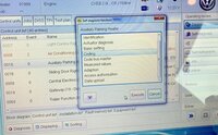
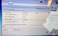
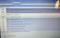
I'm having no luck with ODIS-S. I cannot work out how to flash the heater file... I cannot find an option '042 Flash' or anything flash related via the Control Modules screen.
If I try via the Flash re-programming I don't see any suitable option either - no option to upload a file or anything that suggests to lead me into that option.
I tried all sorts of submenus as well.

Here are some screenshots via Control units
IMG_4367.jpg

IMG_4368.jpg

IMG_4369.jpg

and one via flash reprogramming

IMG_4373.jpg

Any help appreciated.
 
Back
Top