It’s handy when you wait 8 hours for breakdown recovery in sub zero temps on the moors. Sit in the back with your feet up nice and warm and make a brew.I can wholeheartedly recommend the diesel heater, they really do warm the whole van up really quickly.
And it's handy not just when camping. Picking someone up/waiting around for someone with it's cold and don't want to sit there with the engine running for heat? Stick on the diesel heater!
Doing some work inside the van and feeling a little chilly? Stick on the diesel heater!
Minus degrees in the morning and commuting to work at 7am? Stick on the diesel heater (half an hour before you leave) and have a nice toasty warm and defrosted van!
You are using an out of date browser. It may not display this or other websites correctly.
You should upgrade or use an alternative browser.
You should upgrade or use an alternative browser.
Dellmassive`s Camper Van Adventure
- Thread starter Dellmassive
- Start date
more bits inbound thanks to 12v Planet + Screwfix.
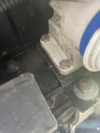
thinking of going with the external EHU IN under the bonnet by the battery . . .
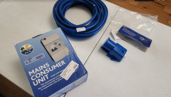
got some 2.5mm 20A Arctic blue cables for the runs. . .

a two way CU . . . . ( the red lamp show incoming reverse polarity L/N apparently)
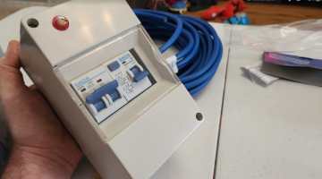
which comes with some paperwork, , ,

...
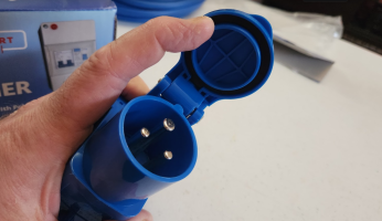
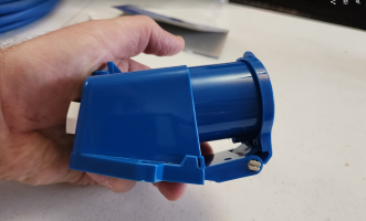
and for outgoing EHU I've gone for this one. . .

...
my thoughts are:
EHU IN under bonnet by battery.
CU passenger seat base. - as no room next to battery.
240v outlet on a 4way fly lead for now - but to be replaced with a twin socket on a seat base back panel.
the idea being no inverter for now, just the EF deltas - so the EHU can charge that
+++++++
BUT, i also want EHU OUT,
that will be run from the EF Delta2 240v output . . .
its a floating inverter, so doesn't need the chassis earth bond.
and i would use EHU extension reals that have built in RCD protection.
so no need to worry about fancy transfer switches..
I'm thinking of just an extension lead style. . . a plug in the van - plugged into the Delta2, which runs external from the van, to the EHU OUT socket.
WHY?
well when camping for a couple of nights or longer we normally have the twin compressor fridges, tea & coffee machine in the side awning.
and normally have to have extensions leads trailing out the passenger window, or slammed shunt in doors. . . which is not ideal.
the plan being when we OFF GRID, the Delta provides the 240v, then we just use the EHU lead run from the external point inro the awning for the above kit.
simples right?
+++++++
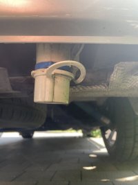
as for location, i first thought up front - next to the EHU IN.?
but now im thinking of at the rear under the the rear bumper passenger side? - cable run could then be out the floor grommet under the seat, then allong the underside of the van to the back bumper location.
that will make it easier to connect to and run into the side awning via its cable entry point.
+++
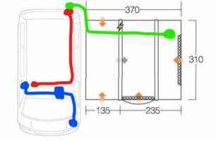
this kind of thing. . .
BLUE is the EHU IN , via the CU to a double socket.
RED is the EHU OUT , from the delta2 (or plugged in to a EHU in socket for EHU loop-through)
GREEN is the external EHU RCD real out to the awning for off grid EHU from the delta2.
+++
separately we will be having the SB230ah + DC-DC charger under the drivers seat - that will trickle charge the Delta2. + 12v stuff.
and decided to defo get a derv heater fitted ( OEM location under van with OEM B-Pillar ducting as both seat bases will be full)
we also have a new AMT12-2 to be used as a start battery trickle charger from the SB230,
solar will be mobile for now as needed and connected via SB50`s
+++

thinking of going with the external EHU IN under the bonnet by the battery . . .


got some 2.5mm 20A Arctic blue cables for the runs. . .

a two way CU . . . . ( the red lamp show incoming reverse polarity L/N apparently)

which comes with some paperwork, , ,

...
and for outgoing EHU I've gone for this one. . .

...
my thoughts are:
EHU IN under bonnet by battery.
CU passenger seat base. - as no room next to battery.
240v outlet on a 4way fly lead for now - but to be replaced with a twin socket on a seat base back panel.
the idea being no inverter for now, just the EF deltas - so the EHU can charge that
+++++++
BUT, i also want EHU OUT,
that will be run from the EF Delta2 240v output . . .
its a floating inverter, so doesn't need the chassis earth bond.
and i would use EHU extension reals that have built in RCD protection.
so no need to worry about fancy transfer switches..
I'm thinking of just an extension lead style. . . a plug in the van - plugged into the Delta2, which runs external from the van, to the EHU OUT socket.
WHY?
well when camping for a couple of nights or longer we normally have the twin compressor fridges, tea & coffee machine in the side awning.
and normally have to have extensions leads trailing out the passenger window, or slammed shunt in doors. . . which is not ideal.
the plan being when we OFF GRID, the Delta provides the 240v, then we just use the EHU lead run from the external point inro the awning for the above kit.
simples right?
+++++++
as for location, i first thought up front - next to the EHU IN.?
but now im thinking of at the rear under the the rear bumper passenger side? - cable run could then be out the floor grommet under the seat, then allong the underside of the van to the back bumper location.
that will make it easier to connect to and run into the side awning via its cable entry point.
+++
this kind of thing. . .
BLUE is the EHU IN , via the CU to a double socket.
RED is the EHU OUT , from the delta2 (or plugged in to a EHU in socket for EHU loop-through)
GREEN is the external EHU RCD real out to the awning for off grid EHU from the delta2.

+++
separately we will be having the SB230ah + DC-DC charger under the drivers seat - that will trickle charge the Delta2. + 12v stuff.
and decided to defo get a derv heater fitted ( OEM location under van with OEM B-Pillar ducting as both seat bases will be full)
we also have a new AMT12-2 to be used as a start battery trickle charger from the SB230,
solar will be mobile for now as needed and connected via SB50`s
+++
I thought the answer to why an EHU out would be to supply you fellow campers with power so you could act like a mobile power station for all us dweebs that don’t have a decent off grid setup 
We have our EHU under the rear bumper and I think it works really well, ours is slightly off centre to the drivers side. I would recommend for in/out, virtually invisible and easy as long as you AREN’T (edit) excessively low
We have our EHU under the rear bumper and I think it works really well, ours is slightly off centre to the drivers side. I would recommend for in/out, virtually invisible and easy as long as you AREN’T (edit) excessively low
Last edited:
Got some pics of the rear EHU, and how it's mounted?I thought the answer to why an EHU out would be to supply you fellow campers with power so you could act like a mobile power station for all us dweebs that don’t have a decent off grid setup
We have our EHU under the rear bumper and I think it works really well, ours is slightly off centre to the drivers side. I would recommend for in/out, virtually invisible and easy as long as you excessively low
Seen one guy had his screwed to a lump of wood underneath.
And for EHU battery chargers.....
I'm thinking I'll just plug in a victron 15A+ to the inside 240v socket, then plug into the 12v side with sb50 Anderson quick disconnect.
So basically a plug and play solution for when it's needed..... No need for a permanent install.
I'm thinking I'll just plug in a victron 15A+ to the inside 240v socket, then plug into the 12v side with sb50 Anderson quick disconnect.
So basically a plug and play solution for when it's needed..... No need for a permanent install.
Do you know for certain if your inverter bonds N and PE lines? If not then any RCD will not work.its a floating inverter, so doesn't need the chassis earth bond.
and i would use EHU extension reals that have built in RCD protection.
RCDs aren't magic make it safe devices, they need to have reasonably specific configuration in your wiring arrangements to work.
From Victron Wiring Unlimited

I have a general feeling of unease whenever an inherently portable and temporary 240v source is connected to structured wiring as if it's the grid. While they are inherently low risk and safe for the designed use (devices plugged in directly to them occasionally) the further you move from that the more the risk rises and adding structural wiring to them can make them less safe as it's something they are not built to do in the way that say a Clayton device is.
interesting, ill have a look.
a fair comment, so i thought id double check.Do you know for certain if your inverter bonds N and PE lines? If not then any RCD will not work.
RCDs aren't magic make it safe devices, they need to have reasonably specific configuration in your wiring arrangements to work.
From Victron Wiring Unlimited
View attachment 241972
I have a general feeling of unease whenever an inherently portable and temporary 240v source is connected to structured wiring as if it's the grid. While they are inherently low risk and safe for the designed use (devices plugged in directly to them occasionally) the further you move from that the more the risk rises and adding structural wiring to them can make them less safe as it's something they are not built to do in the way that say a Clayton device is.
the RCCB in this EHU cable real i have just connects to the live and neutral. - the earth pin links straight through.
it trips when it detects any difference in current flow going out the live core and back in on the neutral core.
so its effectively working without the PE earth.
when the test button is pressed it causes an imbalance in the live/natural and pops the trip.( not sure how it does this with no earth connection?)
Edit: MikesElectricStuff shows it (1min40sec) there is an internal resistor diagonal across the internal current sense coil that causes the imbalance --
rigging it up, and pressing the test button causes the RCCB/RCD to trip out. (even though we have no earth connection - floating inverter)
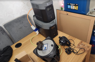
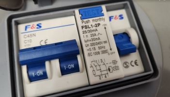
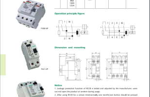
a quick vid showing that working. . .
++++
New video by ESD Lee
 photos.app.goo.gl
++++
just to double check i found this vid from John Ward, one if the Electrical gurus i follow.
++++++++++++
so i think the idea is that even if a fault made the vans chassis live (when using the floating inverter), and you touched it, you wouldn't get a shock as there is no return path to the genset - ie the floating inverter neutral terminal.
which is why Victron say that floating inverters are safer with NO earth connection,. . .
so assuming that you PE+N bonded the inverter to the vans chassis, and you had a fault with the electric kettle , you would get a shock from the kettle and the van. . . . no PE+N bond = no shock.
++++++++++++
but at any point you have external EHU into the van, then that specific EHU feed needs grounding to chassis as there IS a return bath to the Genset ( the GRID)
++++++++++++
so I'm assuming we have the first option below, floating Inverter with no earth.

240v consumer unit earthing
I just found this on the interweb...... To comply with BS7671 sect 721 any PERMANENT 240 volt installation in a vehicle (including caravans and motorhomes etc) should have the incoming mains supply earth bonded to the vehicle chassis. It also worth noting that any metal gas pipes should also be...


++++++++++++++++++++
looks like victron have updated there install guide.
Floating network in boat or vehicle (IT Network)
In a mobile system where an inverter (or generator) is the only power source onecan specifically choose not to use a TT network but to use an IT network.
In an IT network, the phase and neutral are not coupled to another potential like earth.
The voltages created by the independent power source are floating.
A system like this is very safe and simple to install.
If a conductor or housing in this system is touched by a person, no current can flow to earth.
Remember, for current to flow a complete circuit is needed.
In this system the earthing conductor is absent, and the electric circuit to earth is not complete.
This is a similar situation to the safety transformer in a bathroom.
Inverters and generators are in principle nothing more than the source of twopotential differences with a difference of 230 Volt (or 120V).
Touching will not lead to a current flow because the path is incomplete.
It is the same as a bird sitting on an electricity wire.
Be aware that touching both the phase and neutral wire at the same time is always dangerous because then the path is complete.
+++

+++
But, going back to the original question - would the RCD trip with a downstream fault when its connected to a floating inverter?
i can only hope so, but not sure how to safely test it?
so im assuming that a water soaked kettle wouldn't cause the RCD to tip as there was no where for the leakage current to go, but at the same time be safe as there was no chance of getting a shock unless you managed to touch the inverter return neutral, or the van bodywork if the PE+N link was present. (which is why its safer to not have the chassis PE+N bonded on a floating inverter)
but im hoping that with a fault that more of the 25mA trip current could be used in heat or a spark from something going bang? and that would trip the RCD?
im now trying to think of ways to test it. . . .
++++
more goodies from screwfix. . . .more bits inbound thanks to 12v Planet + Screwfix.
View attachment 241928
thinking of going with the external EHU IN under the bonnet by the battery . . .
View attachment 241929View attachment 241930
got some 2.5mm 20A Arctic blue cables for the runs. . .
View attachment 241931
a two way CU . . . . ( the red lamp show incoming reverse polarity L/N apparently)
View attachment 241932
which comes with some paperwork, , ,
View attachment 241933
...
and for outgoing EHU I've gone for this one. . .
View attachment 241934
...
my thoughts are:
EHU IN under bonnet by battery.
CU passenger seat base. - as no room next to battery.
240v outlet on a 4way fly lead for now - but to be replaced with a twin socket on a seat base back panel.
the idea being no inverter for now, just the EF deltas - so the EHU can charge that
+++++++
BUT, i also want EHU OUT,
that will be run from the EF Delta2 240v output . . .
its a floating inverter, so doesn't need the chassis earth bond.
and i would use EHU extension reals that have built in RCD protection.
so no need to worry about fancy transfer switches..
I'm thinking of just an extension lead style. . . a plug in the van - plugged into the Delta2, which runs external from the van, to the EHU OUT socket.
WHY?
well when camping for a couple of nights or longer we normally have the twin compressor fridges, tea & coffee machine in the side awning.
and normally have to have extensions leads trailing out the passenger window, or slammed shunt in doors. . . which is not ideal.
the plan being when we OFF GRID, the Delta provides the 240v, then we just use the EHU lead run from the external point inro the awning for the above kit.
simples right?
+++++++
as for location, i first thought up front - next to the EHU IN.?
but now im thinking of at the rear under the the rear bumper passenger side? - cable run could then be out the floor grommet under the seat, then allong the underside of the van to the back bumper location.
that will make it easier to connect to and run into the side awning via its cable entry point.
+++
this kind of thing. . .
BLUE is the EHU IN , via the CU to a double socket.
RED is the EHU OUT , from the delta2 (or plugged in to a EHU in socket for EHU loop-through)
GREEN is the external EHU RCD real out to the awning for off grid EHU from the delta2.
View attachment 241937
+++
separately we will be having the SB230ah + DC-DC charger under the drivers seat - that will trickle charge the Delta2. + 12v stuff.
and decided to defo get a derv heater fitted ( OEM location under van with OEM B-Pillar ducting as both seat bases will be full)
we also have a new AMT12-2 to be used as a start battery trickle charger from the SB230,
solar will be mobile for now as needed and connected via SB50`s
+++
external EHU OUT. . .

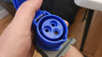
..
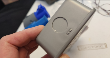
and a metal double socket . . .
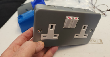
i chose this one as it was sitting there on the shelf right in front of me , and i can fit a 20mm stuffing gland in the end of it, nivce and easy.
...
Yep John Ward and Mike are good references.
Floating systems are inherently safer so long as they are not grounded - in my experience running events that's the common case up to around 3-4 KVs - the only folks I ever saw ground a small system were some radio HAMs and that was because they needed low noise.
However any RCD fitted downstream isn't going to trip with a wiring fault as there is no earth return path - so if the line wire shorts to an earthed metal kettle body there is no connection on the PE, no current flow to earth, no imbalance so no downstream RCD trips. If you are a floating supply you are still reasonably safe - but the RCD is not tripping and you do have a physical fault that would be inherently dangerous on a non floating system. If you want them to trip then you need the PE-N link - you can still do that in a floating system as the output PE is also floating. This is potentially best practise as if you had that physical fault, assumed the inverter wasn't running properly, and then carried the kettle over to your EHU socket and plugged it in... best hope your EHU RCD is wired correctly.
In your situation you're not mixing EHU and inverter mains so the situation isn't too complex, but if you want your downstream RCDs to trip on wiring faults in non double insulated devices they won't without a PE-N link.
Important point is that buying and using a cable with an RCD in it does not act like an electrical lifejacket and save you from all things - you have to think through the earthing and protective devices.
Slightly off topic but similar considerations are why sites limit cable lengths - because in those situations you are exporting a protective earth from wherever it is grounded in the site's distribution. Oddly enough the actual physical ground isn't consistently at one voltage (there's really no such thing as "0v") so the further away you move from the actual grounding point the more likely there is a voltage difference between the PE (which on EHU is your whole van and the case of any non double insulated devices plugged in) and the ground you stand on. I've had a tingle from an EHU point at an event in the past and found something like a 75v difference between "earth" in the socket and the actual ground....
ok time to pre build some of thei kit. . .
the idea is to pre-do as much as possible, then when i have the chance to install it. - maybe at next weekends bank holiday weekender.
we will be camping - but may have the chance to do some install nbits.
starting with the main starter battery pickup and fuse for the main link back to the dc-dc charger.
i went with a 125A MEGA fuse + Holder on the 25mm2 cable,
with 25mm2 cable crimps with 8mm bolt hole, and glued heat shrink.
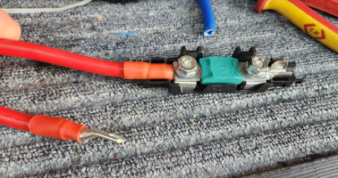
i added some cable sock on the outgoing cable. . . but left it uncrimped so it can be passed through the firewall.
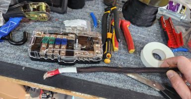
this is the cable i used for the link. . . . 25mm2

with these MEGA fuses. . .
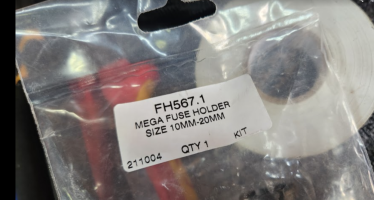
for comparison, this is a MEGA fuse next to a MIDI fuse. . . they are four times the size and can handle the power without getting hot.
but they are large on size so best kept to the main power feeds only.
.
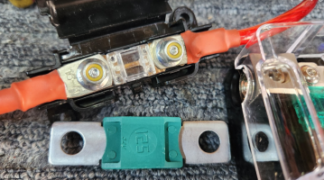
another pic of the MEGA showuing the holdedr..

now linking in the MIDI fuse block and Victron Orion XS 50A DC-DC charger - on 16mm2 cables and a 60A MIDI fuse.
(this is for the leisure battery side under the passenger seat)

a close up of the MIDI fuse box for under the seat. . .
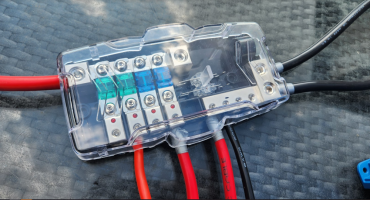 ..
..
.
finished article with the added main NEG points and the SB50 Anderson connector for the EF Delta2.

and here showing the main link cable too. . .
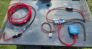

++
thats the prep work done. . .
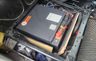
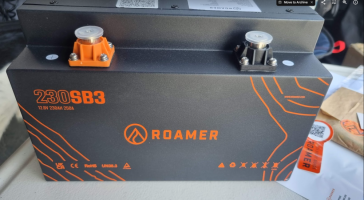
ill take these bits to site, with the SB230 ROAMER Seat Battery - @RoamerBatteries
ill be taking this Roamer SB230 out my battery box . . .
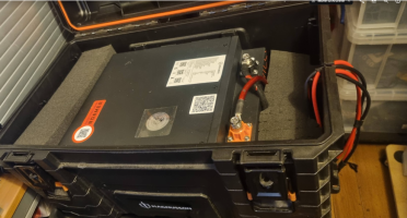
and will be fitting it under the drivers seat. . . .
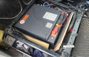
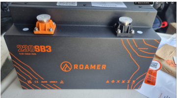

+
check it out. . . . and get 5% Off

 roamer.com
.
.
the idea is to pre-do as much as possible, then when i have the chance to install it. - maybe at next weekends bank holiday weekender.
we will be camping - but may have the chance to do some install nbits.
starting with the main starter battery pickup and fuse for the main link back to the dc-dc charger.
i went with a 125A MEGA fuse + Holder on the 25mm2 cable,
with 25mm2 cable crimps with 8mm bolt hole, and glued heat shrink.

i added some cable sock on the outgoing cable. . . but left it uncrimped so it can be passed through the firewall.

this is the cable i used for the link. . . . 25mm2

with these MEGA fuses. . .

for comparison, this is a MEGA fuse next to a MIDI fuse. . . they are four times the size and can handle the power without getting hot.
but they are large on size so best kept to the main power feeds only.
.

another pic of the MEGA showuing the holdedr..

now linking in the MIDI fuse block and Victron Orion XS 50A DC-DC charger - on 16mm2 cables and a 60A MIDI fuse.
(this is for the leisure battery side under the passenger seat)

a close up of the MIDI fuse box for under the seat. . .
 ..
...
finished article with the added main NEG points and the SB50 Anderson connector for the EF Delta2.

and here showing the main link cable too. . .


++
thats the prep work done. . .
ill take these bits to site, with the SB230 ROAMER Seat Battery - @RoamerBatteries
ill be taking this Roamer SB230 out my battery box . . .

and will be fitting it under the drivers seat. . . .


+
check it out. . . . and get 5% Off

Roamer - Premium LiFePO4 lithium Leisure Batteries
Roamer SMART4, XTREME and HOME - the next generation in 12v 24V and 48V LiFePO4 lithium leisure batteries for campervans, motorhomes and boats. From 100Ah to 460Ah capacity with Bluetooth BMS, Victron GX integration, Active Balancing and low temperature charge protection. 5 Star UK support, 10...
.
.
Last edited:
EHU side of things. . .
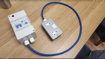
stuffing glands added to the CU + double socket.
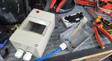
remembering to follow good electrical practice. . .
strip, twist + double back.

and remembering to add a link cable to the metal back-box.
i added a cable tie to stop the cable being pulled back. .

moving over to the CU. . . . .

hooked in + linked in. . .
one stuffing gland for IN & one for OUT.
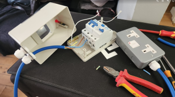
that gets us this so far . . . . .
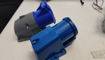
adding io the EHU inlet. .
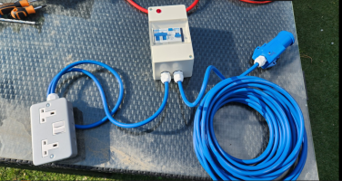
we get this. . . .
thats the prep work done. . .
ill take these bits to site, with the SB230 ROAMER Seat Battery - @RoamerBatteries
ill be taking this Roamer SB230 out my battery box . . .
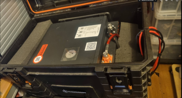
and will be fitting it under the drivers seat. . . .

+
check it out. . . . and get 5% Off

 roamer.com
.
stuffing glands added to the CU + double socket.

remembering to follow good electrical practice. . .
strip, twist + double back.

and remembering to add a link cable to the metal back-box.
i added a cable tie to stop the cable being pulled back. .

moving over to the CU. . . . .

hooked in + linked in. . .
one stuffing gland for IN & one for OUT.

that gets us this so far . . . . .

adding io the EHU inlet. .

we get this. . . .

thats the prep work done. . .
ill take these bits to site, with the SB230 ROAMER Seat Battery - @RoamerBatteries
ill be taking this Roamer SB230 out my battery box . . .

and will be fitting it under the drivers seat. . . .


+
check it out. . . . and get 5% Off

Roamer - Premium LiFePO4 lithium Leisure Batteries
Roamer SMART4, XTREME and HOME - the next generation in 12v 24V and 48V LiFePO4 lithium leisure batteries for campervans, motorhomes and boats. From 100Ah to 460Ah capacity with Bluetooth BMS, Victron GX integration, Active Balancing and low temperature charge protection. 5 Star UK support, 10...
.
I love a nice bit of neat wirework and crimping 
Out of interest what crimpers are you currently using?

Out of interest what crimpers are you currently using?
same here . . .I love a nice bit of neat wirework and crimping
Out of interest what crimpers are you currently using?
i want to be able to run the 50A dc-dc charger at full rate on occasions without worrying about cable and MIDI fuses overheating,
so im going in heavy of the cable gauge for now. . . which means it will stay cool under full 50A load as its 170A rated. but will enable me to double up DC-DC chargers if needed, one of my future upgrades may be twin Victron XS 50A Orion's - so 100A of DC-DC charging - but i need to check the Alternator fitted, as it may only a standard 140A and not the 180A that my work van has.
++++++++++++
im using these. . . Battery cable crimping tool recommendation please
for the big cable and the 25mm2 and 16mm2 crimps im using the big yellow ones. . . TU-22C
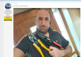
which can be seen here: Battery cable crimping tool recommendation please
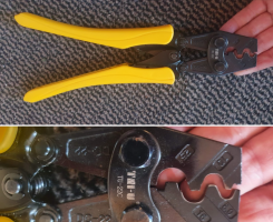
for the smaller 8AWG silicone cable for the SB50 Andersons i use the smaller HS-16 crimpers . .
seen here : Battery cable crimping tool recommendation please

remembering to follow good electrical practice. . .
strip, twist + double back.

Here’s one more: always leave ground (yellow/green) couple of cm longer than live and neutral. Ensures it will be the last one to come off if the cable is pulled.
Indeed, very true.Here’s one more: always leave ground (yellow/green) couple of cm longer than live and neutral. Ensures it will be the last one to come off if the cable is pulled.
And something I normally do at work.
Funny how when it's your own house etc you just make do.
kinda sort of started the install, in a grass camp field, with minimal tools.
..
1st job was battery and rear plate out.
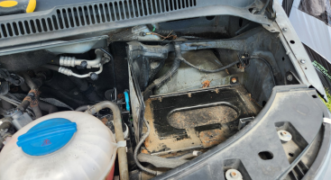
which gets us to this bung, we have to run the cables through this, then into the plenum chamber. ( i cut out a U shaped section large enough to allow the new cables to sit in place so that the cover plate doesnt squash them)
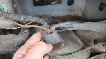
were aiming for this OEM grommet in the bulk head that gets us into the cabin area. . .
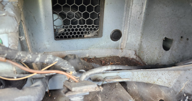
a few bits now on the grass. . . . think I'm asking for trouble here. . .
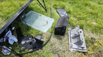
next up was glovebox out and lower plastic trim . . . but TBH i dont think the glovebox needs to come out. . .
the door seal rubber pulled back,
then the rubber floor matt pulled back.
oh and also the chair+base out by removing the 4x floor bolts.

that gets us to the OEM cable tunnel to follow the OEM wire routes from the firewall down the center line,
then off to either drivers or passengers seat.

cutting out the centre of the grommet the cables passed through fine . . . ill deal with water proofing this at a later date ( probably cable tie in place then silicone sealant)

the cables present themselves at the top of the A-pillar. . .

i decided to cable sock the whole length of the red feed cable as it was thin wall type. . . but very thick copper cores, so will be very good at dealing with large currents.
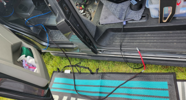
i decided i wanted the EHU over the passenger side.
and 12v over the drivers side. . .

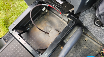
with the floor matt back down we get this. . .
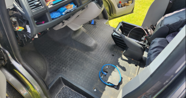
EHU will go in the passenger seat base. . .

Roamer ( @RoamerBatteries ) SB230 seat base battery will be going under the drivers seat, with the Victron XS 50A DC-DC charger and MIDI fuse box.

passenger seat back in we can connect up the CU.


ill be mounting the CU on a board later, and adding a chassis PE earth bond. . . . but for now we have this.
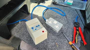
.
then it all went pear shaped. . . . .
the birthday boy wanted to go to the pub for a "couple" of lunchtime beers to celebrate his birthday.
so off we went, crocs and all. . . . .

that put paid to that, after the pub it was a quick scramble to re-assemble the van in case it rained over night...
i was in no fit state to deal with any mechanics or electricals. . .
++++
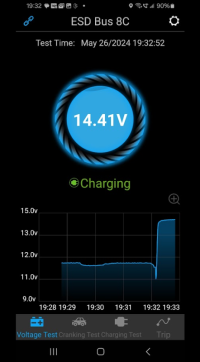
later that night there was a perfect example of why you need a leisure battery system in a camper. . .
after a few nights, the starter battery was done. . .

a quick BM2 check showed the battery down to 11.7v,. . . so i run the engine for 20mins to get some charge back in.
i had the NOCO jumpstarter with me incase of a flate battery, but its best to not let the battery get that low in the first place.
that's about as far as i could go on this occasion. . .
..
1st job was battery and rear plate out.

which gets us to this bung, we have to run the cables through this, then into the plenum chamber. ( i cut out a U shaped section large enough to allow the new cables to sit in place so that the cover plate doesnt squash them)

were aiming for this OEM grommet in the bulk head that gets us into the cabin area. . .

a few bits now on the grass. . . . think I'm asking for trouble here. . .

next up was glovebox out and lower plastic trim . . . but TBH i dont think the glovebox needs to come out. . .
the door seal rubber pulled back,
then the rubber floor matt pulled back.
oh and also the chair+base out by removing the 4x floor bolts.

that gets us to the OEM cable tunnel to follow the OEM wire routes from the firewall down the center line,
then off to either drivers or passengers seat.

cutting out the centre of the grommet the cables passed through fine . . . ill deal with water proofing this at a later date ( probably cable tie in place then silicone sealant)

the cables present themselves at the top of the A-pillar. . .

i decided to cable sock the whole length of the red feed cable as it was thin wall type. . . but very thick copper cores, so will be very good at dealing with large currents.

i decided i wanted the EHU over the passenger side.
and 12v over the drivers side. . .


with the floor matt back down we get this. . .

EHU will go in the passenger seat base. . .

Roamer ( @RoamerBatteries ) SB230 seat base battery will be going under the drivers seat, with the Victron XS 50A DC-DC charger and MIDI fuse box.

passenger seat back in we can connect up the CU.


ill be mounting the CU on a board later, and adding a chassis PE earth bond. . . . but for now we have this.

.
then it all went pear shaped. . . . .
the birthday boy wanted to go to the pub for a "couple" of lunchtime beers to celebrate his birthday.
so off we went, crocs and all. . . . .

that put paid to that, after the pub it was a quick scramble to re-assemble the van in case it rained over night...
i was in no fit state to deal with any mechanics or electricals. . .
++++
later that night there was a perfect example of why you need a leisure battery system in a camper. . .
after a few nights, the starter battery was done. . .

a quick BM2 check showed the battery down to 11.7v,. . . so i run the engine for 20mins to get some charge back in.
i had the NOCO jumpstarter with me incase of a flate battery, but its best to not let the battery get that low in the first place.

that's about as far as i could go on this occasion. . .
Last edited:
Hi @Dellmassive, are you fitting mains charger to charge the leisure battery when on EHU? and if so are you putting it under the drivers or passenger seat?
Similar threads
- Replies
- 17
- Views
- 707
- Replies
- 2
- Views
- 625
- Replies
- 182
- Views
- 21K


