Dellmassive`s Camper Van Adventure

Moving on, Kombi brackets are out. . .

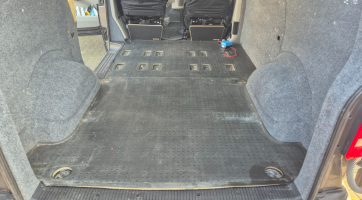
so its time to take out the floor matt.


1742922194900.png


its out now if anyone wants to buy it?

1742922220401.png


time for a quick floor scrub, which reveiled loads of old screw holes from the old ply lining.

and the floor bracket holes.

1742922289613.png

.

1742922302287.png1742922311509.png

so it was hammer and screwdriver time to flatten out the high screw peaks.

1742922347476.png

then zinc primer time. . . with these cool felt paint dabbers.

1742922370379.png

.
spray paint zinc stuff in the cup, the dab away. . .


1742922420401.png

it worked very well.


1742922443491.png


.


ill add in a pic of all the holes primered. .


after this well be filling the screw holes with a dab of Tiger seal,


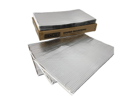
and the larger holes with a square of the DODO sound deadening.


1742922601780.png
 
  • Like
Reactions: CAB
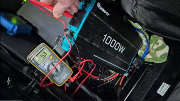
@Dellmassive Are you sure your Renogy is actually N E bonded? That goes against what Renogy technical dept say and how my Renogy is wired: Measuring mine I have 115vac between L and E and 115vac between N and E, when on inverter (I don't use the UPS function) to form 230vac across L and N.
0-3 ohms

from NEG terminal, to inverter case bolts

from NEG terminal to INPUT 3pin PE terminal

from NEG terminal to OUTPUT 3pin PE terminal

from input PE to output PE

basically everything is linked to NEG

1742922734387.png1742923246992.png1742923278869.png1742923266836.png1742922748353.png

++++++++++

i also plugged in my 3pin mains tester - and it said L-N reversed lol. . . .

so i might remove the end cover and swap L & N and retest the 3pin tester.

+++++++++


im not running a CU or RCD in the van, and the van has no E link. - just the inverter with no grid connection.


1742923485147.png


.
 
more bits are arriving. . .

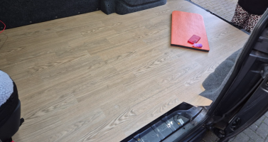
Anteca saftey floor in oak finish. . .

1742923564908.png

..

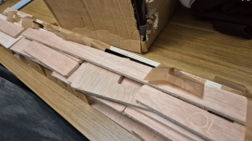
500 million sub floor 9mm kit. . .

1742923593951.png1742923602862.png

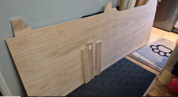
and a 1 piece floor. . . that's actually in two pieces. . . lol

1742923645599.png
 
0-3 ohms

from NEG terminal, to inverter case bolts

from NEG terminal to INPUT 3pin PE terminal

from NEG terminal to OUTPUT 3pin PE terminal

from input PE to output PE

basically everything is linked to NEG

View attachment 280198View attachment 280203View attachment 280205View attachment 280204View attachment 280199

++++++++++

i also plugged in my 3pin mains tester - and it said L-N reversed lol. . . .

so i might remove the end cover and swap L & N and retest the 3pin tester.

+++++++++


im not running a CU or RCD in the van, and the van has no E link. - just the inverter with no grid connection.


View attachment 280206


.
But are your Neutral and Earth pins connected at the output socket?
 
OMG I can see I have some serious studying to decide which inverter I want/need :eek:
You can have any Inverter you like... If it's on its own sockets

It's only when you mix external EHU with internal inverter it becomes an issue re bonding.

Some people run dedicated inverter socket.

Some people fit a transfer switch before the CU.

Load of options depending on what you want.

I'm going simple and having inverter 240 only..... But will add a EHU powered battery charger linked to the LB... There is a slight risk from the EHU cable getting shorted too the chassis, but the EHU RCD will deal with that.
 
@Dellmassive Are you sure your Renogy is actually N E bonded? That goes against what Renogy technical dept say and how my Renogy is wired: Measuring mine I have 115vac between L and E and 115vac between N and E, when on inverter (I don't use the UPS function) to form 230vac across L and N.
Gotcha, I see what you are saying now.

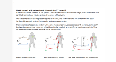
So it's effectively Floating with no N,E bond,... Meaning a L-chassis fault wouldn't trip the down stream RCD.
 
Gotcha, I see what you are saying now.

So it's effectively Floating with no N,E bond,... Meaning a L-chassis fault wouldn't trip the down stream RCD.
Exactly. If id known before purchasing my Renogy I wouldn't have bought it, as although it works for me now it isn't going to be suitable for my future plans.
Have you looked at Stirling in addition to Victron? They do pure sine wave inverters NE bonded with RCD built in and hardwired mains cable out. I've no experience of them myself.
 
You can have any Inverter you like... If it's on its own sockets

It's only when you mix external EHU with internal inverter it becomes an issue re bonding.

Some people run dedicated inverter socket.

Some people fit a transfer switch before the CU.

Load of options depending on what you want.

I'm going simple and having inverter 240 only..... But will add a EHU powered battery charger linked to the LB... There is a slight risk from the EHU cable getting shorted too the chassis, but the EHU RCD will deal with that.

The Renogy comes with a plug, that if you plug into a socket on your EHU setup, automatically stops the inverter outputs and uses the EHU supply so you can just run one AC ring. That’s what I’m planning.

Edit: just seen the previous page…
 
Exactly. If id known before purchasing my Renogy I wouldn't have bought it, as although it works for me now it isn't going to be suitable for my future plans.
Have you looked at Stirling in addition to Victron? They do pure sine wave inverters NE bonded with RCD built in and hardwired mains cable out. I've no experience of them myself.
watched these two last night . .

an interesting incite, , ,

ill be testing mine later.

++++


+++


++++


a floating inverter is still safe according to Victron, with respect to the real earth, i mean all the EcoFlow portable PowerStation's and the like are floating earth.

and if the was a short to chassis, the max potential difference would be 115v, which is what we use on building sites. . and much safer than a 240v PD.


but if you wanted to use traditional RCD in a CU, then agreed a Bonded N-PE would be needed.

also not forgetting that its only the RCD that is effected. . . the MCB and 6A, 16A breakers would still be effective.


+++++


so you takes your choice. .


Renogy floating inverter with MCB protection but no RCD protection,

or

Victron bonded with RCD & MCB.


.
 
Ok double you turn...

Had a look at the alternative options.

Had a look at the combi units, ie inverter chargers.

Decided we don't need and 240v EHU in 96% of the time.

So decided to go with the inverter only option.

But 3kw ISH to convert the requirements.

And one that could be N-PE bonded, so we can make full use is the RCD protection in the consumer unit.

Decided that the 4% of time we need the EHU 240v in ..... It will be a stand alone battery charger clipped to the LB.

So after liking over the options...


I went for..


...


...


..


...


...

Screenshot_20250326_083222_Chrome.jpg

...

Yep, back to#team blue.


3000va, 2400watt continuos.

130% overload for 30mins

6kw peak starts.

N-PE bonded option.

But needs 90mm2 cable for 0-5m

Or twin 70mm2 - jeez


Recommended battery bank is 400ah.

So we have also ordered a second sb230 gen 4 to go under the passenger seat .. that gives me us a 460ah battery bank. From the guys over at @RoamerBatteries

.
.
 
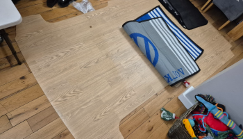
Dry fit the 9mm play floor - check.

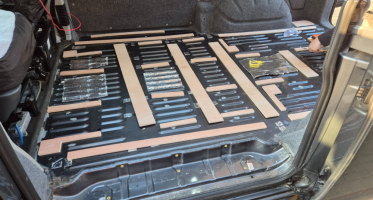
layout the battens - check.

1743015459774.png

.

cover holes with sound deadening stuff. . .

1743015497180.png

.


Sikaflex battons down . .

1743015528896.png

through in 9mm floor quick.

the add the Altro, to weigh down the floor so the Skilafex sticks.

1743015599359.png


then add loads of stuff from the living room to weigh down the floor.


.


Sorted.
 
Dry fit the 9mm play floor - check.

layout the battens - check.

View attachment 280383

.

cover holes with sound deadening stuff. . .

View attachment 280384

.


Sikaflex battons down . .

View attachment 280387

through in 9mm floor quick.

the add the Altro, to weigh down the floor so the Skilafex sticks.

View attachment 280388


then add loads of stuff from the living room to weigh down the floor.


.


Sorted.


@Dellmassive

You started to wear leopard print stuff, or have you had a little helper, helping?
:cool:
1743016527554.png 1743016581981.png
 
OkeyDokey Karaoke . . lets carry on.

the bank holiday seems long ago, so its time to carry on.


so it was battery back out and start tidying up. . .

i added some cables ties to stop the loom from moving. . .

View attachment 244329


and cut out some more of the Rubber bung, as the cables showed some sign of being squashed. . .

View attachment 244330


battery back in it was time to end off the main 12v power feed.

View attachment 244331

cable stripped back ready for a MAXI fuse holder end . . . . just look at those coper cores, this is some beefy cable.

View attachment 244332

which brings me to my first problem, trying to get the cable, crimp end, and two hands on the crimper. . . i needed 8 hands,

this is defo where the ratchet or hydro crimpers are a benifit. . .

but these crimps are the half-open type, so need to have a crimper that rill roll the open ends back in to make a good strong connection.


View attachment 244333

i got it on after some faff. . . done the heatshrink, then added the rest of the fuse holder that was already pre-made last week.

I've dropped in a 125A fuse for now.

View attachment 244335


fuse holder all closed and we are ready to move on,

View attachment 244336

+++++++++++++++++++

back in the cab we have this chassis earth stud and domed cap nut.

which is great, but no good for me fitting the 230ah seatbase battery, as the battery pushes down hard on the floor matt and caused a pressure point wher the dommed nut is pressing into the bottom of the battery - no good.

so it had to go,

i didnt have the grinder with me while camping. . . . . but did have it today.


20seconds later - it was gone.


ill paint the exposed metal with a touchup pen i have.

View attachment 244342


so floor mat back down we have this . . . .

View attachment 244343


the battery fits in nice, but i wasnt happy with the main power feed being that close to the seat base and battery metal work. . .

View attachment 244344


so i took the battery back out, . .

grabbed some 20mm copex flex tube, . . . .

View attachment 244345

and slid on about 30cm of tube to protect the area . . . .

View attachment 244346


i got carried away after that, . .

but the next step was to add in the prepped charger and MIDI fuse box that we built last week. . . .

the plan was to velcro the MIDI fusebox at the fron of the battery,

then have the DC-DC, Shunt and 12v fusebox down the sides . . .

View attachment 244347


i used a seat bolt for the main chassis ground, with a 25mm/10mm lug on the cable,

remove some of the paint, and bolt down - ill redo this better at later date, but just to get it in for now it will ok.

View attachment 244348


top down it looks like this. . .

no shunt fitted at this stage. . . .

View attachment 244349


the second main NEG cable from the MIDI fusebox/busbar will connect to the main battery NEG.

+++++++++++++


now to the main starter feed. . . .


the 50A Victron Orion XS will take a 16mm2 cable max, so i needed some was to decouple the 25mm2 incoming cable.

i made up a short 16mm2 link lead. . . .

View attachment 244351

and bout the 25mm2 cable up and over the battery and ties to the seat base using those handy holes. . .

View attachment 244352


then decided to use one of these NEG busbars to join the two. . .

View attachment 244353

one good thing, (not sure if its an advantage yet) is that they are crimpless - so just cut/strip/stuff in hole and tighten up.

no crimp lugs needed.

so main starter feed in this side. . .

View attachment 244354

and 16mm2 out this side. . . .

View attachment 244357

which gives us this . . . .


pic limit . . .

continued.


@Dellmassive - no concerns about running the 12v/240v alongside each other?


.
 
Back
Top