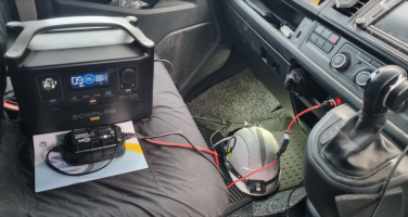
Hi @Dellmassive, are you fitting mains charger to charge the leisure battery when on EHU? and if so are you putting it under the drivers or passenger seat?
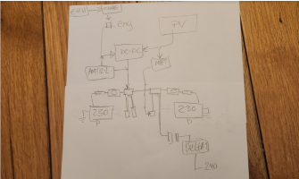
yes,

looking back to the original sketch here : Dellmassive`s Camper Van Adventure


1716982106125.png


ill have a quick disconnect on the starter battery , and the leisure battery.

so ill be able to connect to either just by plugging it in.

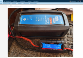
i have a few Victron IP22 & IP65 chargers that i can use,

but seeing as i dont normally use EHU there is no point perminantly fitting it,

so ill have it as a temp mobile option to just plug and pluy.


however - if i was to hard wire it and perm fit it. . .


i would mount the charger under the passenger seat hard wired into the CU,

then run the 12v feed under the carpet to the drivers side and connect into the 12v fusebox.. . . either on the starter side ot the leisure side of the DC-DC charger.

another option is to fit twin chargers,

a 5A for the starter and 15A for the leisure, - again both under the passenger seat.


.


1716982421230.png


++++


personally ill be using a AMT12-2 b-b trickle charger to keep the starter topped up, from the 230ah lithium under the seat. ( charged via 50A victron dc-dc or mobile solar )

so i wont need a separate starter battery EHU charger,


1716982556554.png

.


you can also setup a mobile plug and play EHU charger via the 12v sockets (upto 8A) - [Guide] Battery Maintainer (for Starter battery) -- How I Done It --


1716982630189.png


.


you can also connect one EHU charger up to the starter battery - provided you have a DC-DC charger,


then use that to charge both batteries. . . victron chargers are best for this as you can tweek the charge profile to stop the DC-DC from cycling. - [Guide] DC-DC Charger (for leisure battery) -- How I Done It --


1716982778129.png1716982792144.png
 
Last edited:
OkeyDokey Karaoke . . lets carry on.

the bank holiday seems long ago, so its time to carry on.


so it was battery back out and start tidying up. . .

i added some cables ties to stop the loom from moving. . .

1717528087702.png


and cut out some more of the Rubber bung, as the cables showed some sign of being squashed. . .

1717528144863.png


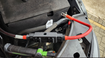
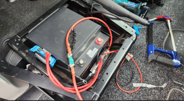
battery back in it was time to end off the main 12v power feed.

1717528197377.png

cable stripped back ready for a MAXI fuse holder end . . . . just look at those coper cores, this is some beefy cable.

1717528249077.png

which brings me to my first problem, trying to get the cable, crimp end, and two hands on the crimper. . . i needed 8 hands,

this is defo where the ratchet or hydro crimpers are a benifit. . .

but these crimps are the half-open type, so need to have a crimper that rill roll the open ends back in to make a good strong connection.


1717528484355.png

i got it on after some faff. . . done the heatshrink, then added the rest of the fuse holder that was already pre-made last week.

I've dropped in a 125A fuse for now.

1717528665784.png


fuse holder all closed and we are ready to move on,

1717528705505.png

+++++++++++++++++++

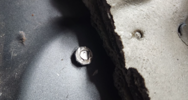
back in the cab we have this chassis earth stud and domed cap nut.

which is great, but no good for me fitting the 230ah seatbase battery, as the battery pushes down hard on the floor matt and caused a pressure point wher the dommed nut is pressing into the bottom of the battery - no good.

so it had to go,

i didnt have the grinder with me while camping. . . . . but did have it today.


20seconds later - it was gone.


ill paint the exposed metal with a touchup pen i have.

1717528921207.png


so floor mat back down we have this . . . .

1717528969723.png


the battery fits in nice, but i wasnt happy with the main power feed being that close to the seat base and battery metal work. . .

1717529024351.png


so i took the battery back out, . .

grabbed some 20mm copex flex tube, . . . .

1717529063147.png

and slid on about 30cm of tube to protect the area . . . .

1717529099166.png


i got carried away after that, . .

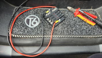
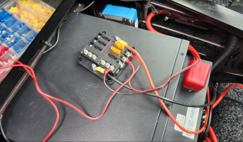
but the next step was to add in the prepped charger and MIDI fuse box that we built last week. . . .

the plan was to velcro the MIDI fusebox at the fron of the battery,

then have the DC-DC, Shunt and 12v fusebox down the sides . . .

1717529159225.png


i used a seat bolt for the main chassis ground, with a 25mm/10mm lug on the cable,

remove some of the paint, and bolt down - ill redo this better at later date, but just to get it in for now it will ok.

1717529324931.png


top down it looks like this. . .

no shunt fitted at this stage. . . .

1717529364883.png


the second main NEG cable from the MIDI fusebox/busbar will connect to the main battery NEG.

+++++++++++++


now to the main starter feed. . . .


the 50A Victron Orion XS will take a 16mm2 cable max, so i needed some was to decouple the 25mm2 incoming cable.

i made up a short 16mm2 link lead. . . .

1717529547206.png

and bout the 25mm2 cable up and over the battery and ties to the seat base using those handy holes. . .

1717529599943.png


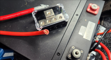
then decided to use one of these NEG busbars to join the two. . .

1717529651312.png

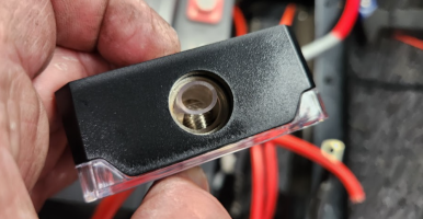
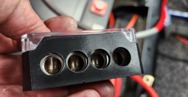
one good thing, (not sure if its an advantage yet) is that they are crimpless - so just cut/strip/stuff in hole and tighten up.

no crimp lugs needed.

so main starter feed in this side. . .

1717529736063.png

and 16mm2 out this side. . . .

1717529768658.png

which gives us this . . . .


pic limit . . .

continued.


.
 
which gives us this. . .


1717529841553.png

so thats the main 50A dc-dc feeds sorted . . . the aim is to run this system 50A flatout without smoking the cables.

this should do it fine.


1717529881271.png

so far we have this, and almost ready to connect the battery in . . . . using the other 125A MAXI fuse that we made up the other week. . .

1717529965522.png


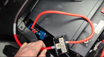
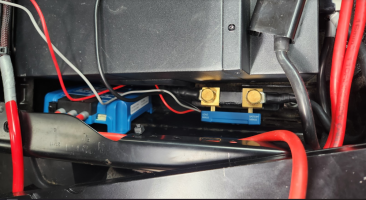
the MAXI fuse holder fitted under the seat lip perfect, so i cabled it in,

and connected the battery. . .


1717530118170.png
1717530094698.png

previously we had added the 50A SB50 Anderson to the MIDI fuse box,

this will be used for now as any of the following via plug-N-play :

EcoFlow Delta 100w trickle charger - OUT,
Solar PV MPPT - IN
EHU charge - IN
any 50A feed - OUT

1717530301244.png


looking down at the front this is what it looks like. . .

i havent fitted a master isolator switch ATM, but i can switch the battery OFF via the APP, . . . . so not exactly proper isolation, but a sudo-isolation...


I've had the battery charge/discharge disabled while installing this so far to prevent any slip/trip/oops moments - remember with lithium safety first !!!


so now almost ready to switch it on.

1717530330296.png


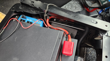
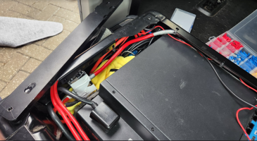
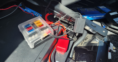
looking from the top down of the left, we have the DC-DC charger and POS busbar block, . . . all just loosely tucked in there for now,

with a few cable ties to stop the cables from rubbing or chafing.

1717530619062.png


on the right we have the main POS feed coming in. . . . excuse the filth, i havent had time to spring clean the seatbase yet,

but they all look like that anyway - i bet yours does too?

and that isn't even my filth. . . that the previous owners excreted bodily disgustingness`, plus half the sand from some surf bums beach somewhere.

:mexican wave:

1717530799679.png


right now for the power up. . .

both main batteries connected and switched on. . .


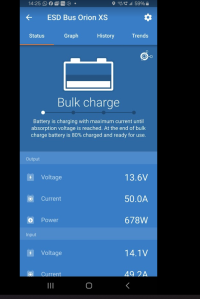
i started easy to see how we go on, 30A to start, setting via the Victron APP.

1717530912430.png1717530948652.png

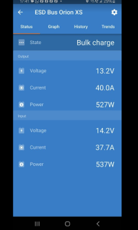
all was looking good after a few mins, so bumped it up to 40A . . .


1717530990067.png

all the time watching the battery BMS too, which showed the 40A charge,


yep 6% !! - this was the battery we used at last weeks 5day camp trip, i set the shut off at 5% as i didnt want to go lower than that. . .

so we started at 5% and now going up from there. . . .


1717531022104.png

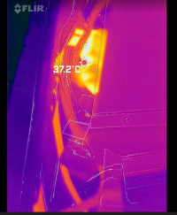
now time to check the thermals. . .


the seatbase battery looked good. . .

1717531139495.png


the charger showed some heating, but still bellow 50degc, so im happy with that. . .

1717531183185.png

the MIDI fusebox looked ok. . .

1717531248527.png


checking the starter battery fuse connection, all looked ok. . .

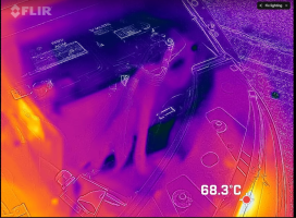
then i see this 93DegC . . !!!

1717531294328.png


zooming in on itm, it was 150Deg C !!!!! WHAT !!

1717531326091.png


having a quick look, it was the THQ V3 LED headlights,

well the resistor pack on the top,

the heat cam was seeing it through the grill...


nuts !!!

but nothing to do with the battery any my new connections. . .

1717531411855.png


moving back to the battery - cool as a cucumber.

1717531450100.png


so i velcroed on the MIDI fusebox, . . .


.
 
so i velcroed on the MIDI fusebox, . . .


1717531506578.png


which leaves us with this. . .

1717531545951.png


that was that for this day . . .

+++++++++++++++++++++

the next day i was ready for more ------------

now we are adding the VICTRON IP65 SUNT, a 12v ATC fusebox, a Victron CERBO-S GX and a MIFI box so the GX can talk to the interwebs. . .

1717531703781.png

the shunt dropped in weel down the left side, id left the NEG cable long for this reason,

so i cust cut the cable in half and added two 25mm/10mm crimps and heatshrink.

1717531801525.png

i prepped the 12v ATC fuse box with some 4AWG silicone flexy cable. . . this will be powered from a 30A MIDI fuse, from the other fusebox, . .

1717531879255.png


and started adding in circuits, . . .

one for the CERBO GX, that will live over on the RHS,

and one for the SHUNT main power feed, i cut off the 20mm 1A glass fuse and wired into a ATC blade fuse with a crimp ring terminal. . .


1717531978672.png


i added the SHUNT second feed to the starter battery BLOCK, i had its own 1A 20mm glass fuse and holder, so that was fine . . . .

1717532069345.png

gotta show the love for the forum . . . @Pauly

1717532171129.png


the extra circuits no wired in . . . ( i re made off those NEGS, they went link that from all the moving about)

1717532228750.png


the smaller 12v fuse box tucked down the front RHS, so i added some foam to keep it from moving for now.


1717532338515.png


and on the LHS i added some tape round the main POS block and put a wash towel between it and the main NEG shunt below it. . . ( all for temp)


1717532451565.png


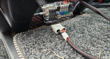
i also added some cable - sock to the SB50A connection . . .

1717532479290.png

nice. . .

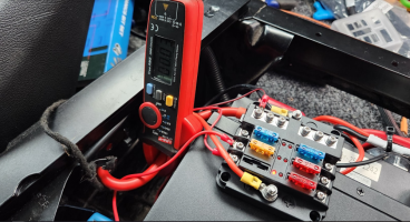
grabbing the current meter for some quick testing. . .

1717532583834.png


everything seemed to test good. . . .

+++++++++++++++++++++++++++++++++++++++++++++

This bit gets a bit techy -----------

one thing i did note, and was expected, was that the Orion XS charger shut down after 5mins of engine running.

this was due to the basic setting of the "engine running auto detection" . . .

basically the T6 smart alternator ramps down and the 14,2v charging voltage drops down to 13.2v or whatever. and the Vic` XS switches OFF.

so,

you need to go into the Victron settings and reduce the start stop voltage setting for the charger to kick back in.

but thats not the full story.

with the Alternator giving the 13.2v and the XS adjusted to running . . . . and set at 50A, you just cant get it.

it was hovering around 20A. . . . why?

the only way to get the full 50A again was to make the alternator output a higher voltage. . .

now this is a catch 22 moment.


you would think - that the Vic XS would pull 50A from the system, causing a volt drop and curent draw that the van will see by refencing the Starter battery shunt data and the Alternator output. . . but it doesnt !! - it just wont incease the Alt output voltage.

so what happens is the Vic XS tries to pull more power, but detects the voltage drop, so throttles back - net result is it throttles back to around 20A, where it will happily sit.

+

well thats no good !!!! - i have a 50A charger !, and want 50A !!, and i want it now !!!!! even though the engine is just sitting there ticking over at 800rpm.

yep i hear you - me too.

and its an easy fix:

all you need to do is set the T6 fan blower to position #2 ( or above)

or just turn of the headlights.

yep its that simple. . . .

basically the vans energy management system in the vans BCM/ECM will detect that you want the fans or headlights ON. . .

it will switch on the load and at the same time up the Alternator power to accommodate the request.

the more you turn on - the more the Alternator will output - and the higher the system voltage rises. .

now back to the Vic XS. . . .

well it immediately sees the higher system voltage and starts ramping up with it.

Boom !!! 50A charge rate while ticking over at 800rpm - and yep, all i done was to set the blower fans on #2 ( or headlights )

dont ask me about the VW energy management algorithms on the T6 . . .i have no idea - this is just what i worked out in my testing.

so if you want big power from your dc-dc make sure you turn some stuff on.

edit: while writing this, im wondering why the system is not detecting the power draw by the dc-dc charger and not increasing the alternator power to compensate? - as surly it should? - anyway thats a conumdrem for another day. . .


told you it was getting techy.


++++++

so heres a pic of a cute puppy to smooth your sore head , , , , ,

1717533875757.png


++++++++++++++++++++++++++++++

.
 
next day - more testing. . . .


i added a BM2 battery monitor to the small fuse box, . .

1717534049987.png

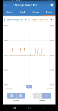
setting the Orion XS to 30A. . .

1717534095697.png

we can see 27A coming from the main battery POS link,

1717534129734.png


we see 30A going into the battery from the Battery BMS. . .

1717534179389.png

thats cool,

so ramping up fo the full 50A . . . .

1717534220820.png1717534232064.png

which is confirmed at the battery. . .

1717534263245.png


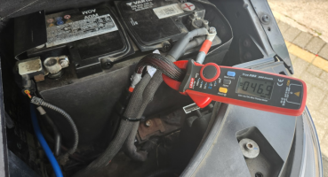
now showing 46.9A at the starter. . . .

1717534296963.png


and the same 46A odd at the LB NEG terminal. . .

1717534344382.png


keeping an eye on things. . .

1717534374554.png

i run it at 50A for 30mins. . . . and all was good. . .


so seats back in. . .

1717534439515.png

.


1717534464009.png

and ready for another day. . .

.


.
 
Moving the rear load area LED lights over to the LB. . .

the previous owner fitted roof LED lights - which was nice.


and added this 20mm three way rocker switch, lovely.

that basically simulated the OEM three way switch in the rear. . .

we have:

II - OEM curtsey lighst
0 - OEM OFF
I - OEM ON with 15min timer


1717534597712.png1717535181083.png


which basically is the same as factory switches. . . . but this was running my starter battery flat.

more info here - LED Interior Cargo Lights - How I Done It.


***************************************************************************************
Factory Non-LED 3 wire setup:

(brown) - earth point left a-pilar
(brown/red) - connection 1 main harness (BCM switched neg 0v)
(red/black) - positive connection 1 main harness (BCM timed +12v) ( 7.5A fuse 24 holder C)
****************************************************************************************

Factory LED 2 wire setup:

(brown/red) - connection 1 main harness (BCM switched neg)
(red/black) - positive connection 1 main harness (BCM timed +12v)( 7.5A fuse 19 holder C)

****************************************************************************************


lets see how they done it. . .

pulling the headlining we have the three wires. . .

1717534799391.png

that go up tio the top of the B-pillar,

where they handily connect to the four LED light, sweet.

1717534845829.png

tracing them back we can see that they just used the OEM three wires and from the front light and pulled them forwards. . .

1717534905119.png


ok, job done,

so all i need to do is replace the OEM timed starter battery POS with a 24/7 LB feed. . .

im also planning on adding some USB chargers to the B-pillar,

so ill run a nice beefy cable from the LB fuse box, and run the lights + other stuff.

i found some of this stuff. . .

1717535029508.png

a nice fat bit of copper twin,. . .

1717535053994.png

i run it from the top of the B-pillar,

down to the floor matt. . .

1717535091817.png

then along the floor between the two mat joins. . . ( check out that crud + sand under the flooring, Yuck!!! )

1717535120137.png

over to the drivers side, the up into the seatbase, and connected to the small 12v fusebox. .

switching on the rear lights, we now see 1A being drawn from the LB, where before it was coming from the starte battery. . .


a nice easy fix. . .


1717535284034.png

following the cable back up to the lights, we can see the same 1A going direct to the 4x LED lights,

so 250mA each . .


1717535342912.png


this is also varified on the newley fitted Vic SHUNT. . . now showing a 1A load being drawn.

1717535377027.png


obviously some clips got broken . . . . so anyone know where to get some of these from that are not total pants and just snap by looking at them>?

roof join bar:

1717535465548.png


B-Pillar top - long

1717535486775.png

B-Pillar white - short.

1717535519436.png

.

once again all back together. . . . now light LB powered lights. . .

1717535561202.png


.
 
Coming up Next :

we have some BadBoy WIFI,

USB 3 / PD charge Ports,

THQ rear reading lights,

THQ rear roof lights . . .


its all ordered and on its way. . . .


++++++++


sneeky peeky. . .


1717535854693.png1717535904611.png

1717536049748.png1717536113409.png

Screenshot 2024-06-15 151119.jpg

1717536127427.png1717536093702.png1717536027357.png1717535995931.png1717535949324.png1717535930413.png1717535883120.png
 
Last edited:
not forgetting the AMT2-12 - (starter trickle charger)

that needs fitting.


1717540391175.png


....


++++++++++++++++++++


and we are looking at he Victron multiplus 12/3000/120-32 as a possible inverter & EHU Charger.

but sticking with the EcoFlow Delta2 for the mains side for now..


1717540524133.png1717540586568.png1717540558822.png


+++++++++


and we defo going for the Diesel heater.

so watch this space, nothing booked in yet. - but we need the LB fitted before we had the heater fitted.

now we have a power source to run the heater its now possible.


1717540803538.png
 
so i velcroed on the MIDI fusebox, . . .


View attachment 244382


which leaves us with this. . .

View attachment 244383


that was that for this day . . .

+++++++++++++++++++++

the next day i was ready for more ------------

now we are adding the VICTRON IP65 SUNT, a 12v ATC fusebox, a Victron CERBO-S GX and a MIFI box so the GX can talk to the interwebs. . .

View attachment 244384

the shunt dropped in weel down the left side, id left the NEG cable long for this reason,

so i cust cut the cable in half and added two 25mm/10mm crimps and heatshrink.

View attachment 244385

i prepped the 12v ATC fuse box with some 4AWG silicone flexy cable. . . this will be powered from a 30A MIDI fuse, from the other fusebox, . .

View attachment 244386


and started adding in circuits, . . .

one for the CERBO GX, that will live over on the RHS,

and one for the SHUNT main power feed, i cut off the 20mm 1A glass fuse and wired into a ATC blade fuse with a crimp ring terminal. . .


View attachment 244388


i added the SHUNT second feed to the starter battery BLOCK, i had its own 1A 20mm glass fuse and holder, so that was fine . . . .

View attachment 244390

gotta show the love for the forum . . . @Pauly

View attachment 244393


the extra circuits no wired in . . . ( i re made off those NEGS, they went link that from all the moving about)

View attachment 244394


the smaller 12v fuse box tucked down the front RHS, so i added some foam to keep it from moving for now.


View attachment 244395


and on the LHS i added some tape round the main POS block and put a wash towel between it and the main NEG shunt below it. . . ( all for temp)


View attachment 244396


i also added some cable - sock to the SB50A connection . . .

View attachment 244397

nice. . .

grabbing the current meter for some quick testing. . .

View attachment 244398


everything seemed to test good. . . .

+++++++++++++++++++++++++++++++++++++++++++++

This bit gets a bit techy -----------

one thing i did note, and was expected, was that the Orion XS charger shut down after 5mins of engine running.

this was due to the basic setting of the "engine running auto detection" . . .

basically the T6 smart alternator ramps down and the 14,2v charging voltage drops down to 13.2v or whatever. and the Vic` XS switches OFF.

so,

you need to go into the Victron settings and reduce the start stop voltage setting for the charger to kick back in.

but thats not the full story.

with the Alternator giving the 13.2v and the XS adjusted to running . . . . and set at 50A, you just cant get it.

it was hovering around 20A. . . . why?

the only way to get the full 50A again was to make the alternator output a higher voltage. . .

now this is a catch 22 moment.


you would think - that the Vic XS would pull 50A from the system, causing a volt drop and curent draw that the van will see by refencing the Starter battery shunt data and the Alternator output. . . but it doesnt !! - it just wont incease the Alt output voltage.

so what happens is the Vic XS tries to pull more power, but detects the voltage drop, so throttles back - net result is it throttles back to around 20A, where it will happily sit.

+

well thats no good !!!! - i have a 50A charger !, and want 50A !!, and i want it now !!!!! even though the engine is just sitting there ticking over at 800rpm.

yep i hear you - me too.

and its an easy fix:

all you need to do is set the T6 fan blower to position #2 ( or above)

or just turn of the headlights.

yep its that simple. . . .

basically the vans energy management system in the vans BCM/ECM will detect that you want the fans or headlights ON. . .

it will switch on the load and at the same time up the Alternator power to accommodate the request.

the more you turn on - the more the Alternator will output - and the higher the system voltage rises. .

now back to the Vic XS. . . .

well it immediately sees the higher system voltage and starts ramping up with it.

Boom !!! 50A charge rate while ticking over at 800rpm - and yep, all i done was to set the blower fans on #2 ( or headlights )

dont ask me about the VW energy management algorithms on the T6 . . .i have no idea - this is just what i worked out in my testing.

so if you want big power from your dc-dc make sure you turn some stuff on.

edit: while writing this, im wondering why the system is not detecting the power draw by the dc-dc charger and not increasing the alternator power to compensate? - as surly it should? - anyway thats a conumdrem for another day. . .


told you it was getting techy.


++++++

so heres a pic of a cute puppy to smooth your sore head , , , , ,

View attachment 244400


++++++++++++++++++++++++++++++

.
Good to know this re the charging whilst idling - although I'm sure you mentioned before to turn on the lights or a heated seat to force the alternator to up it's output.

The Orion XS manual does mention that the alternator output may be reduced when idling.

Where would that beast of a multi plus fit?!
 
Yes I've noted it in the past..

But always good to refresh the ideas..... And go over it in my head.

As for the inverter, we (me & the missus) were going over locations for an inverter...I had a 2000w Renogy inverter to hand as a size demo....

We tried under the passenger seat, but it stick out the front or rear.

We tried parallel on the back of the seat base, but interfered with the main space we used.

One possible option was on the side wall under the side window behind the drivers seat.

We're still set up as a kombi plus OVANO.

And that's also where the delta 2 lives when we head out for tripped in there van.

The delta2 fits perfect down the side of the seat base against the side wall. (Triple singles in the rear)

But the delta 2 max is a bit wider, so won't for on the same gap..... It has to sit more forward or behind the drivers seat..

....


Long story short we decided best location was tucked away on sidewall under second row seat..... Although cable management might be an issue.....
It's a trade off in location versus keeping the DC cables as short as possible.

So decided to stick with the delta 2's for now.

And wait till we all the pop top, rib need, and kitchen cabinets, and build it in there somewhere.

But if the urge gets too great then the side wall it is as a temporary measure.


...

The size is the problem...

If we want to be completely ridiculous, which we do.....
Then I need to run the twin fridges, 60w each. Plus some tablet and phone chargers 20w. And usb battery packs 20w... That about 160w.

Then add the 1400w coffee machine. And for some reason, every time the coffee machine is switched on the 1000w kettle also gets switched on.

So that's that's 2560w peak.

That will overload the Renogy 2kw, and the victron 1.6kw I have....

The delta 2 just about handles it.... And the delta 2 max takes it on worries.

The multiplus 3kva is 2400w plus some surge so seems the perfect size ... It also has a 120A EHU charger, and will trickle the starter battery on EHU..... Plus it's a big blue shiny box..... And we all know that I love the victron kit.

So for now we sticking with the delta 2.

But the victron 3kva is sitting on the side lines waiting to take the show.

That also opens up the possiblity of cooking with electric, assuming enough battery capacity or DC DC chargers.....I suppose you could run the engine...... But our cook ups regularly last well over half hour, so would be a big drain on the battery s. And ultimately just burn diesel instead of gas.
 
  • Like
Reactions: CAB
We have a Mastervolt Dakar Inverter Charger on the narrowboat and it's brilliant. Space is an issue in a T6 vs 65 foot of boat but as a solution they Just Work - whatever power source you have whatever power draw you want they do the right thing.

I've just realised that with 2 seatbase LiFePo you have twice the usable capacity of the 4x110Ah lead acid house bank on the boat... :oops:

 
IMG_4923.jpegMaybe one for the spotted! Was this you thread but I think I’ve seen your camper Lee!
:think smile bounce:

Seriously though, since travelvolts retired there is a bit of a gap in the market for this sort of thing. Ever thought of making a living out of this stuff?
 
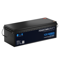
I'm sure there's still room in the back of his van for a 608Ah battery (aka 'The Beast') :D
View attachment 244469
right so two of those will see me sorted. . . False floor me thinks?


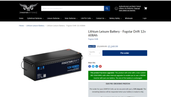
2x608ah is 1216ah ( 15,564wh )

£1249.99 each so £2500 for both.


£2500 / 1216ah is £2.05 per ah - so not to bad in the grand scheme of things.

+++++++++

its so heavy they dont even tell you the weight lol.

+++++++++


Lithium Leisure Battery - Fogstar Drift 12v 608Ah​


QUICK SPECS
  • Nominal Capacity 608Ah
  • Nominal Voltage 12.8V
  • Recommended Charge Voltage 14.4V
  • Max Cont. Discharge 250A
  • L(640mm)*W(245mm)*H(220mm)
  • Cell Assembly
  • Weight
  • IP67 Rated
  • All Fogstar Drift terminals are all M8 in size, 1.25 pitch, 12mm. All of our Drift Leisure batteries come with bolts and terminal posts as standard.
  • The Fogstar Drift 12V 608Ah is suitable for use with inverters up to 3000W in size.


+++++++++

1717581165726.png


++++++++++


i think that twin 50A DC-DC chargers - all day long,

and defo the Victron Multi P 2 - 120A EHU charger.

two of those will take an age to charge up.
...


just dont know where to fit them - suppose they would have to go on the RHS under window, maybe one on top of the other?


.
 
  • Love
Reactions: CAB
We have a Mastervolt Dakar Inverter Charger on the narrowboat and it's brilliant. Space is an issue in a T6 vs 65 foot of boat but as a solution they Just Work - whatever power source you have whatever power draw you want they do the right thing.

I've just realised that with 2 seatbase LiFePo you have twice the usable capacity of the 4x110Ah lead acid house bank on the boat... :oops:
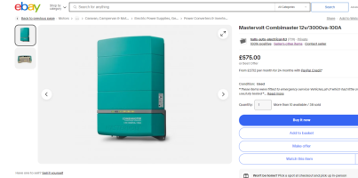
looks like this is the equivalent. . .


1717581961010.png

+++++++

some cheap ones on ebay . . . .

and slightly smaller than the Victron.


1717583231301.png


+++


im fairly certain that the MASTER VOLT stuff is white label COTEK gear. . .

well at least on the inverter side. .

I've had numerous COTEK inverters over the years and they are very good. . .


+++++++++++

1717583638718.png

+++


1717583698854.png
+++++++++++


+++
 
Last edited:
Back
Top