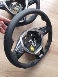
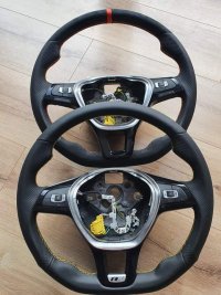
[Guide] How To Retrofit MFSW And Cruise Control To T6 Eu6 2019 Startline - Also Hacking DSG Paddles For CCS

Also if you are wondering like I was initially why possibly changing the horn wire for the ECU signal on pin 11 works, it is because non MFSW and MFSW have different looms. Non MFSW is wired to use horn in pin 11 of the stalk connector but MFSW is wired to have ECU connection / GRA wire there. And instead sends horn signal via LIN on the (in my case) blue white wire in the black connector of the wheel loom.

Also I keep saying GRA (short for Geschwindigkeitsregelanlage) it means Cruise Control in German - I had read a few hundred posts on a German forum, went cross eyed and now it has partly brainwashed me lol
 
Last edited:
Reference the point you highlighted, taking information from everything I have researched over the past few weeks;

Correct you shouldn’t need to do point 4 as the GRA signal from ECU to Stalks should already be present on pin 26 of the stalk connector.

You remove horn wire from pin 11 on stalk connector then move the GRA wire from 26 to pin 11 on the connector.

You then need to run two wires from pin 9 and 10.

Pin 10 goes to BCM under the dash pin 36 for MFSW LIN bus connection.

Pin 9 goes to a switched 12v power supply to power the wheel (people seem of often use ignition 12v on headlight light switch).

The OP is saying to remove the CCS stalk specific wires as you cannot have stalk ccs wired in and mfsw ccs wired in it will conflict in the ecu. You can reuse the wire on 26 which is the GRA as mentioned above.

You then need to do the coding in this thread to instruct the ECU that mfsw is fitted.

Good luck.
Install wire in pin 9 and 10. Use wire 26 in pin 11 .Should I remove wire 27,28,29,30,31 and insulate them? Or can they stay in connector?

Thanks for all the help :)
 
You mean these?
View attachment 139828
Those lines were in VCDS Auto-Scan engine section Freeze Frame Data which @T6_FunBus posted earlier >HERE<

Re the coding - to me they look correct. However, we haven't looked into BCM adaptations - though not expecting any surprises in there.

Working hypothesis at the moment:
As there are only two communication wires - one to ECU, one to BCM - and both respond to some buttons - this suggests both those wires are good. However, for some reason either the ECU or the BCM is not happy with on/off message - either the button itself sends crappy messages or there is interference - thus the proposal to use different +12V supply. Or ground?​

Well, might be too ambitious interpretation but if we look into timestamps of the faults >HERE< the BCM has manifested the fault at 17:35:54, the ECU seems to have received the manifest at 17:35:57 and finally at 17:35:58 ECU has interpreted the error message and decided not co-operate any further. Does this give us the clue to concentrate on on/off button to BCM communications - why it's not happy? View attachment 139844

Greetings, there was an additional wire spliced into the 12v light switch wire. Chris and I recalled there was a second wire already there when adding the ccs +12v. Must be something to do with the 1st owner from it being an ex Service vehicle.

I desoldered and removed this wire, and made a fresh connection for the light switch and ccs 12v wire.

Result? Same, no ccs active.

Measured 12v connection at light switch with volt meter, 0.00 with key off. 11.5 with ignition on but not started. 12.5 but will spike to 13.5+ when smart alternator kicks in, then settles with engine running at a solid 12.5v.

I am ‘happy’ at this point from readings that its a decent switched 12v to the wheel so didn’t run a new 12v.

Also disconnected the 12v supply to wheel, all functions work but no ccs, same symptom as it being connected - not surprising though, ccs is disabled, so removing the 12v supply wouldn't make a difference.

Did try battery reset also.

Maybe the codes need clearing. Pondering the next step.

Thanks for the advice.
 
  • Like
Reactions: mmi
Install wire in pin 9 and 10. Use wire 26 in pin 11 .Should I remove wire 27,28,29,30,31 and insulate them? Or can they stay in connector?

Thanks for all the help

The guide seems to suggest that yes; but I would wait for someone who has done a stalk conversion or knows for sure to comment

I am still troubleshooting my own install at present lol.
 
Well, thank you for doing all the legwork and sharing. Indeed a puzzling challenge. Just remains the ground -

Maybe the codes need clearing.
I don't believe so but of course can't be 100% sure. Cycling ignition should be enough give a fresh start (when fault is not present any more).

Desperate times -
What about MFSW button illumination - it follows dash buttons illumination brightness control? Turns off when lights off (=DRL only)? Works only with ignition on (unlike the dash buttton illumination)?

Even more desperate suggestions -
Would the CC come to life
(1) when no MFSW button illumination (DRL only)​
(2) when MFSW illumination at max - probably should adjust prior to turning ignition on​
(3) when MFSW illumination at min - probably should adjust prior to turning ignition on​
 
Well, thank you for doing all the legwork and sharing. Indeed a puzzling challenge. Just remains the ground -


I don't believe so but of course can't be 100% sure. Cycling ignition should be enough give a fresh start (when fault is not present any more).

Desperate times -
What about MFSW button illumination - it follows dash buttons illumination brightness control? Turns off when lights off (=DRL only)? Works only with ignition on (unlike the dash buttton illumination)?

Even more desperate suggestions -
Would the CC come to life
(1) when no MFSW button illumination (DRL only)​
(2) when MFSW illumination at max - probably should adjust prior to turning ignition on​
(3) when MFSW illumination at min - probably should adjust prior to turning ignition on​

Sorry its been a while, have been busy with work and other stuff.

MFSW illuminates with lights turned as with the rest of the dash. But, I tested, and it also lights up even with the 12v wire disconnected from the light switch to pin 9? And all buttons for stereo and mfd work with that 12v wire at light switch disconnected? So i assume illumination and regular mfw switch power comes from the standard clock spring loom somewhere else?? Assume the live from the light switch therefore is only for the ccs on / off power supply / 12v feed for signal from switch? #confused.

I cannot see any brightness adjustment.

I haven’t had chance to remove wheel and check the ground yet, but the loom had two brown wires, and the wheel only had one pin for ground, so both brown wires are joined together using same ground.

Not sure if one of those brown wires was for ccs or just mfsw and horn, not sure. I think I read on other threads and posts other people had connected both grounds together? Not sure.

Thanks.
 
Last edited:
  • Like
Reactions: mmi
FYi, this was the wheel and loom as supplied.

The loom was wrong, as the blue wire for the horn was on seperate spade connector, not in the black mfw connector. So @Dav-Tec had to cut and re-pin to correct pin in black mfw connector for horn to work.

I think @Dav-Tec checked mfw loom against a wiring diagram and it seemed to be ok, but that being the case, it seems the wheel came with the incorrect T6 loom? Could it be a chance that the mfw loom used isn’t quite right for the ccs?

PFA, unfortunately all wires are not clearly visible, but shows what the loom sort of looks like. I can’t recall if the black connector had three or four wires before dav-tec added the horn wire.

You can see original wheel and loom pic by sender before shipping. Then the later one will all buttons as recieved after I decided to change ccs buttons.

99CA952E-91C8-49B6-B8CE-2A96830C95FE.jpeg

7993D75C-C048-46CA-8017-A3F51CFA92E3.jpeg

EAABDEF4-C3F1-428C-8F4A-E816C5A736C2.jpeg

737F9EEF-6589-46FD-85F3-46FA2AA7B7F0.jpeg
 
  • Like
Reactions: mmi
The wiring needed repinning due to the loom not being quite correct. However with the buttons working for the radio I'm not convinced it's a loom issue. I spoke with @Pauly the other day and he also feels it could be the buttons at fault. I'm currently trying to get a cheap set for us to test the theory but finding some sensibly priced at the minute is somewhat difficult.

Have you got access to obd11 or carista etc
 
From what I've read deeper on, the 12v is purely to signal the ECU. The lights being turned on etc on the wheel is done through the LINbus
 
The wiring needed repinning due to the loom not being quite correct. However with the buttons working for the radio I'm not convinced it's a loom issue. I spoke with @Pauly the other day and he also feels it could be the buttons at fault. I'm currently trying to get a cheap set for us to test the theory but finding some sensibly priced at the minute is somewhat difficult.

Have you got access to obd11 or carista etc
Hmmm, yes s/h wheels command a premium

Sort of, but not regularly, a chap in town has obd11 but is out of town a lot.

Cheers
 
From what I've read deeper on, the 12v is purely to signal the ECU. The lights being turned on etc on the wheel is done through the LINbus
Ahh that makes sense then, basically if I disconnect that 12v then the wheel reacts and functions exactly the same as it does even with it connected. So I guess as you say just for the ccs signal then.
 
I've not given up on your wheel buddy just had a bit on with my knee op but it is still very much on my radar. @mmi is right if the fault clears it should reset with an ignition cycle. Don't forget the cycle starts with the key being removed from the ignition barrel.

Also I'm waiting on a price for a brand new set of buttons direct from TPS
 
Last edited:
I've not given up on your wheel buddy just had a bit on with my knee op but it is still very much on my radar. @mmi is right if the fault clears it should reset with an ignition cycle. Don't forget the cycle starts with the key being removed from the ignition barrel.

Also I'm waiting on a price for a brand new set of buttons direct from TPS
Blimey, no worries thanks, hope the OP went OK and you are recovering.

I’ve been hunting for a cheap SH set for us to try at some point, but then keep thinking they may come from a broken wheel lol. I did that once with my old merc, bought a sh floor shifter box, and it didn't fix the issue, I was 90% sure it was the issue though and thought I’ve gotta try one more, found another sh one and it worked!
 
Partly why I'm waiting for TPS to get back to me. It's an expensive way of being certain but if they're new they should work. I'm convinced it's the buttons
 
Reference the point you highlighted, taking information from everything I have researched over the past few weeks;

Correct you shouldn’t need to do point 4 as the GRA signal from ECU to Stalks should already be present on pin 26 of the stalk connector.

You remove horn wire from pin 11 on stalk connector then move the GRA wire from 26 to pin 11 on the connector.

You then need to run two wires from pin 9 and 10.

Pin 10 goes to BCM under the dash pin 36 for MFSW LIN bus connection.

Pin 9 goes to a switched 12v power supply to power the wheel (people seem of often use ignition 12v on headlight light switch).

The OP is saying to remove the CCS stalk specific wires as you cannot have stalk ccs wired in and mfsw ccs wired in it will conflict in the ecu. You can reuse the wire on 26 which is the GRA as mentioned above.

You then need to do the coding in this thread to instruct the ECU that mfsw is fitted.

Good luck.
In pin 36 it was not any wire. But i supose pin 10 goes to 36 anyway?
 
Sorry its been a while, have been busy with work and other stuff.

MFSW illuminates with lights turned as with the rest of the dash. But, I tested, and it also lights up even with the 12v wire disconnected from the light switch to pin 9? And all buttons for stereo and mfd work with that 12v wire at light switch disconnected? So i assume illumination and regular mfw switch power comes from the standard clock spring loom somewhere else?? Assume the live from the light switch therefore is only for the ccs on / off power supply / 12v feed for signal from switch? #confused.

I cannot see any brightness adjustment.

I haven’t had chance to remove wheel and check the ground yet, but the loom had two brown wires, and the wheel only had one pin for ground, so both brown wires are joined together using same ground.

Not sure if one of those brown wires was for ccs or just mfsw and horn, not sure. I think I read on other threads and posts other people had connected both grounds together? Not sure.

Thanks.
Thanks. Yes indeed it was a shot in the dark. As the steering wheel buttons are illuminated via LINbus the reasoning behind was to alter the PWM (pulse width modulation) signal which illuminates the buttons, and the LINbus data presumably rides on that signal - just to see if the CC would have miraculously have started to work.

I believe we have confirmed the ground connections with all the trials.

Also the "missing" brightness control explains a difference in the BCM coding (byte 21, bit 1="1" ==> dimming button lights via fixed value = no brightness control by light switch).

Re the dash button brightness control @Dav-Tec @T6_FunBus next time you hook up the VCDS perhaps you could try BCM adaptation channel 45 to verify that it is the channel controlling dash button brightness (for vans without brightness control). Most likely the current value is 80 (channel accepts 0..100). Just to feed my curiosity please.​

Well, yet another desperate proposal is to try coding byte 29 to "60" (now "40"). However, both values seem to exist in T6 BCM codings (with MFSW)... so it shouldn't matter.

Anyways, would appreciate if you could post the BCM adaptation map - just in case... and for future reference.

Could his instrument cluster be an issue with it being the very basic one? I've never retrofitted to a van with these clocks in and I doubt it would cause an issue but at this point I'm open to ideas.
Just documenting - from factory the MFSW was available only with the instrument clusters with analogue fuel gauge and engine coolant gauges (MFD Plus, MFD Premium).

I can't see how the cluster would be the issue - all the buttons are "active" except the CC on/off communicates only with the ECU.
 
In pin 36 it was not any wire. But i supose pin 10 goes to 36 anyway?

Yes, I believe 10 must go to 36 for mfsw even if nothing is present on that BCM pin already (from what I have read).

May be worth you writing up your installation steps thus far so someone better qualified than me can comment, as I am only going from what I have read / researched :)

The OP in this thead at the start did the full conversion with steps I believe you are doing right now.
 
Thanks. Yes indeed it was a shot in the dark. As the steering wheel buttons are illuminated via LINbus the reasoning behind was to alter the PWM (pulse width modulation) signal which illuminates the buttons, and the LINbus data presumably rides on that signal - just to see if the CC would have miraculously have started to work.

I believe we have confirmed the ground connections with all the trials.

Also the "missing" brightness control explains a difference in the BCM coding (byte 21, bit 1="1" ==> dimming button lights via fixed value = no brightness control by light switch).

Re the dash button brightness control @Dav-Tec @T6_FunBus next time you hook up the VCDS perhaps you could try BCM adaptation channel 45 to verify that it is the channel controlling dash button brightness (for vans without brightness control). Most likely the current value is 80 (channel accepts 0..100). Just to feed my curiosity please.​

Well, yet another desperate proposal is to try coding byte 29 to "60" (now "40"). However, both values seem to exist in T6 BCM codings (with MFSW)... so it shouldn't matter.

Anyways, would appreciate if you could post the BCM adaptation map - just in case... and for future reference.


Just documenting - from factory the MFSW was available only with the instrument clusters with analogue fuel gauge and engine coolant gauges (MFD Plus, MFD Premium).

I can't see how the cluster would be the issue - all the buttons are "active" except the CC on/off communicates only with the ECU.
Adaptation values is difficult as we live 3 hours apart. Unless there's a member closer that can plug in. Unless Carista or OBD11 can do the same?

I can't either but I'm running out of ideas and it's driving me to distraction not knowing. I'm currently trying to get hold of a cheap set of buttons I can ship @T6_FunBus see if that works. Can't get new ones I went to order a set from TPS and they told me they're not available to order ATM.
 
Yes, I believe 10 must go to 36 for mfsw even if nothing is present on that BCM pin already (from what I have read).

May be worth you writing up your installation steps thus far so someone better qualified than me can comment, as I am only going from what I have read / researched :)

The OP in this thead at the start did the full conversion with steps I believe you are doing right now.
I am going to code Tomorrow so if the shit works I will write down in detail what I have done.
 
Correct
Yes, I believe 10 must go to 36 for mfsw even if nothing is present on that BCM pin already (from what I have read).

May be worth you writing up your installation steps thus far so someone better qualified than me can comment, as I am only going from what I have read / researched :)

The OP in this thead at the start did the full conversion with steps I believe you are doing right now.
Correct Pin 10 goes to 36 on EU6 vehicles
 
Back
Top