[Guide] Mobile Solar Panels ? . . . - How I Did It -

@Dellmassive - Sorry to keep with the questions - I've done a fair bit of reading on this, without shedding much light on it........
On a dull day (like here today), would you expect the 100W panel to register no voltage on a multimeter? It briefly shows a figure which then returns to zero (meter set to 20V). It would show the current - only around 0.5A, which matched the reading on the display when run through the PWM controller. This was the same for any combination of wiring, so my cables are fine. Should I not expect a Voltage reading if really overcast, even though there is current (or is it the brief reading which drops to 0)?

@boxelder

It depends on the panel . . .

but normally with a bight day you should see some voltage, 12v, 18v maybe 20v? - BUT - you will see next to NO current. - soo effectivly the panel is unable to power anything.

I've done some examples here: I've picked out 3x panels to test.

its a overcast day (London - march 21) but fairly bright outside with no direct sun light.


1615371480720.png


.

1st: Lensun 100W

layed out on floor with volt meter direct across the panel,

1615371695851.png

we get VOC : 21.29vdc


1615371725770.png

then metering the current . . . we only get ISC 0.22A or 200mA - so basically no power - 4w open circuit

1615371940679.png


+++

2nd : next up a 50W BlueFusion Foldup panel.

1615371994585.png


VOC we get 20.43vdc

1615372041911.png

ISC we get again 0.16A or 160mA -

1615372084192.png


+++

3rd : Next up we have a 100W Renogy Foldup panel.

VOC is 19.23vdc


1615372150101.png
1615372170147.png

ISC with the panel shorted we get, 0.43A or 430mA

1615372232853.png

1615372254581.png

+++

so thats three different panels, from three different manufactures all tested togeter.

if its a bright day the panel should show some voltage when disconnected from anything.

but will have next to no current available.

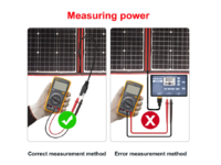
if the panel is connected to a controller the voltage will be pulled low and it might not be possible to get a reading . . . . so this test must be done with the PV panel disconnected.


+++


When its bight and sunny, you will see the same VOC voltage, but you will get the full ISC current . . . . so you will see for example VOC 20vdc across the panel and meter ISC 6A coming from it.

this is now here the Watts come from . . . W=V*A.

before on a cloudy day we had no Amps . . .

Now on a sunny day we have the Amps . . . so (w=v*a) (120w = 20v * 6a)


.


.
 
Last edited:
Hmmm, that's what I was expecting, and the current from mine is similar, under similar skies, to yours. Can't get a voltage reading though. I know the meter works, as tested across the battery terminals and a 9V battery. I'll persevere. Thanks again.
 
Hmmm, that's what I was expecting, and the current from mine is similar, under similar skies, to yours. Can't get a voltage reading though. I know the meter works, as tested across the battery terminals and a 9V battery. I'll persevere. Thanks again.
post a couple of pics for us to see . . the full panel, the meter and connection.

The thing is you need a circuit to get current . . . you cant have a current reading without a measurable voltage. . . .

but a cloudy day is not good for any solar work or tests . . . You need sunshine really. (or a 500w / 1000w halogen lamp shining on it)
 
@boxelder . . .

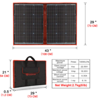
looking at the kit . . - https://amzn.to/3bxso8H

they show the:

VOC @ 22.50vdc
ISC @ 6.35A

so you should be able to see some VOC from the panel in strong daylight.

+++

Dokio 100W 18V PORTABLE FOLDABLE Solar Panel Kit (54 * 73cm, 2.7kg) Monocrystalline(HIGH Efficiency) with CONTROLLER 2 USB Output to Charge 12V Batteries...


1615375300210.png

1615375434209.png
 
Yeah, that's how I'm testing it. The only thing strong about today's sky is the wind driven rain. I'll try again when this storm buggers off.
 
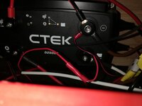
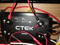
So, I'm getting 20.3V from the panel and the same voltage with all the cables connected - tested with the meter on the solar in (+ve) and -ve terminals on the CTEK. Ctek works fine via the alternator etc, but no amber light for solar and no charging apparent. I'm seeing up to 20V/1A through the PWM croc clipped direct to the battery, which is showing as charging a bit on the battery monitor.
Does the CTEK have a minimum current for solar to work? I get the flashing green light indicating current saving mode (no charging).
Can it be tested by running a DC charger or something to it?
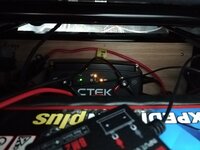
Apologies for the less than tidy wiring........

IMG_20210311_120819.jpg
IMG_20210311_112510.jpg
 
Last edited:
So, I'm getting 20.3V from the panel and the same voltage with all the cables connected - tested with the meter on the solar in (+ve) and -ve terminals on the CTEK. Ctek works fine via the alternator etc, but no amber light for solar and no charging apparent. I'm seeing up to 20V/1A through the PWM croc clipped direct to the battery, which is showing as charging a bit on the battery monitor.
Does the CTEK have a minimum current for solar to work? I get the flashing green light indicating current saving mode (no charging).
Can it be tested by running a DC charger or something to it?
Apologies for the less than tidy wiring........

View attachment 107764
View attachment 107765


The solar input spec is 23voc max. - but doesnt say a mine current to start? - just voltage 5v above aux battery .

1615487623915.png

you could try using a fused humper wire to jump the starter battery voltage up to the solar input . .


1615487752006.png


or use a separate charger to inject power to the solar port . . . just note that the grounds need to all be common.


are you 100% sure that all crimps and connections are metal to metal and that you are getting 20V from the panel. and that the 20v is connected to the solar input and ground?

maybe try a different ground for the solar neg to test? . . . just hold it on.


when we had this before it was due to a bad ground connection on the d250 and a bad crimp on the solar input side.
 
when we had this before it was due to a bad ground connection on the d250 and a bad crimp on the solar input side.
Yeah, I read through all those threads - they're about all that shows up when you google for info.
I get the 20.3V reading when the meter is contacting the allen bolt heads on the CTEK and the same reading on the ring terminals before connecting to the CTEK, so pretty certain it's reaching the controller. Good call on trying a different ground - I'll try that. Cheers.
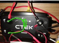
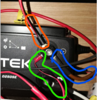
what are these three for? (solar, chassis grnd + ?)

1615488820131.png

maybe just add in a 4th cable , extra test cable and hold in on a seat bolt or similar - to test. ( as a new temp ground )

but it is also possible that the 1Amp just isnt enough to kick in the charger?

maybe try to add some extra light energy on the panel? - to boost up the current available from it?

might be worth a email to CTEK about the D250SE and current needed to start the charge?


+++


FYI

I've just sent CTEK support an email - lets see if they come back.


+++
 
what are these three for? (solar, chassis grnd + ?)

View attachment 107837

maybe just add in a 4th cable , extra test cable and hold in on a seat bolt or similar - to test. ( as a new temp ground )

but it is also possible that the 1Amp just isnt enough to kick in the charger?

maybe try to add some extra light energy on the panel? - to boost up the current available from it?

might be worth a email to CTEK about the D250SE and current needed to start the charge?


+++


FYI

I've just sent CTEK support an email - lets see if they come back.


+++
The one you've highlighted red is the solar connection, blue is to chassis stud and green is the ground from the little IGN live cable.

Yeah, I've emailed them too and will wait for a decent spell of sun. Really don't want to be removing seat etc again #lazygit
 
The one you've highlighted red is the solar connection, blue is to chassis stud and green is the ground from the little IGN live cable.

Yeah, I've emailed them too and will wait for a decent spell of sun. Really don't want to be removing seat etc again #lazygit


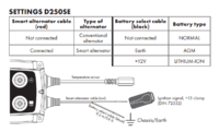
"green is the ground from the little IGN live cable" - eh? whats that then? CTEK battery select cable?

black to GRND for AGM battery type?

and you have the small CTEK RED cable to a IGN fuse? (for smart alt?)

1615489902199.png
 
"green is the ground from the little IGN live cable" - eh? whats that then? CTEK battery select cable?

black to GRND for AGM battery type?

and you have the small CTEK RED cable to a IGN fuse? (for smart alt?)

Correct, yes - connect to ground/-ve to select AGM battery.

Everything else works exactly as it should. Let's see what those helpful Swedes suggest, as it's beginning to do my swede in :thumbsdown:
 
CTEK have replied:

"50W is needed and you can connect the cable from the alternator to the solar panel input, it should work just fine.

regards
Jerry"

Edit:

50w @ 20.3v would be 2.4A.


So they saying you need more sunlight before the ctek kicks in.
 
Cheers fella - you got more than me:

"Hi Andy
the minimum voltage is really low (9V), i.e. it should start charging if was needed and the input power was there. Do you have the PWM regulator in between the charger and the solar panel? That would be a problem."

"50W is needed" - Pretty sure I had it connected when it was giving 4A in the sun the other day - ~80W. Time will tell.

Do Renogy, Victron etc have such high min W requirements?
 
Most MPPT units just state a min of 5v above the battery voltage to start....then 2v above to carry on.

Suppose you will have to wait for more sun.

In the meantime, just try the jumper trick to fool the ctek into thinking it has PV voltage....it should start charging. (Maybe run the engine for a few mins first to raise the starter battery and give it a surface charge)
 
this got me thinking . . . so i thought id test it . . .


"Most MPPT units just state a min of 5v above the battery voltage to start....then 2v above to carry on." - lets see.


What does it take to switch on the MPPT?

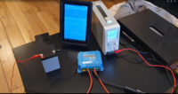
the setup:
Bench power supply,
Victron MPPT 75/15 & 100/30
12v battery.

(yes i know its not fused, its was just a temp test and i was very carful & its a low power battery and PSU)

we are using the variable PSU to feed the PV side of the solar controller.

1615542774660.png

+++

we start with a PV voltage below the battery voltage (11.1v) - as expected the state is OFF.


1615542848928.png

+++

Next we have a voltage equal to the battery - state is still OFF.

1615542900523.png


+++

Next we have a PV voltage (15.2v) above the battery voltage (12.69v) but bellow the 5v threshold - state OFF.

1615542979605.png


+++

as soon as we exceed 5v above the battery voltage the MPPT comes to life and state switched - ON.

1615543030477.png

+++

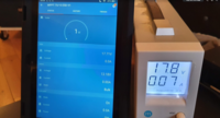
Note that as long as the PV voltage stay above the 5v threshold . . . we can keep the MPPT running, even down to 1W !!!!! (17.8V @ 0.07A)

1615543131954.png


+++

Conclusion . . as expected the Victron performed to spec. - even down to 1W !

ON at 5v above battery voltage.

OFF below 2v threshold.

+++
 
Last edited:
Next up - Same test with the bigger Victron 100/30

1615543388184.png


+++

below battery voltage - state OFF.

1615543420626.png


+++

5v above battery voltage - MPPT state - ON.

1615543456961.png

+++


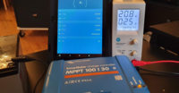
up to max the lab supply can put out : 20V . .

1615543499020.png

+++

dropping down to below the 2v threshold - MPPT switches OFF.

1615543556942.png


+++

Conclusion (same as above) . . as expected the Victron performed to spec. - even down to 1W !

ON at 5v above battery voltage.

OFF below 2v threshold.

+++


i enjoyed this test . . . i think ill test some of the other Solar controllers i have, and look at upgrading the Bench supply


....
 
Further reply from CTEK:
"Hi Andy

Sounds like you should have some charging with the described setup.
You can try to check the functionality of the panel input with a battery.
As jerry says the minimum voltage is 9V for this input and more important the max voltage is 23V. Higher voltage would damage the solar input circuit.
Try to check the solar input with this as the only input."

So I moved the alternator input to the solar, and everything worked as it should.
Conclusion - the CTEK needs a fair bit of solar power to kick in - 50W suggested by them, so ~ 2.5A from my panel which seems to give around 20.5V.
I'll wait for the weather to be less Cumbrian.
Thanks for your help working through this @Dellmassive - what this testing shows is that you'll get more juice via the Victron MPPT boxes than the CTEK, as looks like they'll kick in much sooner.

IMG_20210312_162155.jpg
 
Next up - Same test with the bigger Victron 100/30

View attachment 107895


+++

below battery voltage - state OFF.

View attachment 107896


+++

5v above battery voltage - MPPT state - ON.

View attachment 107897

+++


up to max the lab supply can put out : 20V . .

View attachment 107898

+++

dropping down to below the 2v threshold - MPPT switches OFF.

View attachment 107899


+++

Conclusion (same as above) . . as expected the Victron performed to spec. - even down to 1W !

ON at 5v above battery voltage.

OFF below 2v threshold.

+++


i enjoyed this test . . . i think ill test some of the other Solar controllers i have, and look at upgrading the Bench supply


....
The New Lab Power supply is in (30v 10A) . . . :mexican wave:

1615640477435.png

time to get testing . . .

PSU : https://amzn.to/3eDCNBE

Cable set : IGNPION 0.15”(4mm) 5PC Banana Plug to Crocodile Alligator Clip Test Probe Multimeter Probe Test Lead, Lead Wire Silicone Cable,39.37”(100cm) (5pcs colors): Amazon.co.uk: Car & Motorbike

.
 
Back
Top