[Guide] Mobile Solar Panels ? . . . - How I Did It -

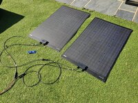
Next up same test . . . . but with the two Lensun panel in series . . . . (110w + 110W = 220W)

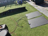
heres the setup:

20200521_161230.jpg

the two panels in series:


20200521_161345.jpg

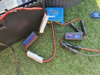
and connected with two power meters, one on the PV side and one on the Battery side.

20200521_161547.jpg


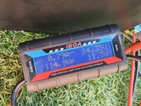
first up PV side we have 39.6V @ 0.4A

20200521_161559.jpg

and battery side is float again . . . @ 14.3v


20200521_161612.jpg

turning on the 30A air pump loaded the battery dropping the voltage to 12.5v . . . .

causing the MPPT to kick into BULK mode . . @ 4.9A


20200521_161811.jpg


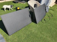
next up was to angel the panels . . .


20200521_161932.jpg


which gave us a bit more . . . . @ 7.2A

20200521_162000.jpg


and just for clarity, to get this 7.17A on the battery side we have this on the PV side. 33.44v @ 3.22A


20200521_162003.jpg


and finally the BM2 shot . . .

Screenshot_20200521-161152_Battery Monitor.jpg
 
OK so testing of the BlueFusion 50W panel started properly today.
As a bit of background, I have never played with, owned, used or even thought about using a solar panel until I bought my T6 in January. I did an electronics HNC as an apprentice but have not worked in that type of industry for more than 25 years, i.e. I have a basic understanding of electrics/electronics but I’m not a practitioner. I’m comfortable making up cables and tracing basic faults but i am far from an expert.

I plan to do three different tests as follows:
  1. BlueFusion panel, using supplied PMW controller, connected to the Starter battery via cigarette socket
  2. BlueFusion panel, using supplied PMW controller, connected to Leisure battery via cigarette socket on leisure circuit
  3. BlueFusion panel, connected directly to CTEK 250SE solar input. I.e not using the supplied PMW controller but using the CTEK inbuilt MPPT controller)
Today was test 1, PMW controller connected to Starter battery via cigarette socket.

I took a snapshot of the BM2 readings before starting a little before 7AM this morning when I connected the panel up and laid it out on the roof of the van. At this point in time there was no sun on the van. It was around 9AM before the sun hit the van and fully covered the panels. Then I just left it alone all day until I disconnected it at about 6PM. I forgot to take a BM2 snapshot before disconnecting so the one I have is from a little while later after i had opened doors a couple of times so will show a slightly lower voltage than at the end of the test would have

Here’s the results:

BM2 readings before test:
View attachment 70657
BM2 traces during test period (top is starter battery, bottom is leisure battery)
View attachment 70658

BM2 readings afterwards:
View attachment 70659

I think this shows quite nicely that a decent charge starts around 9AM when the panel is in full sun, before that it is minimal. By around 9.15 the Starter is sufficiently charged that the CTEK kicks in and then turns on and off for the next 2/3 hours charging the leisure battery. Not sure what happens around 11.30, possibly the PMW controller stepping down into maintenance charge but the Starter stays relatively constant until it slowly starts climbing up around 3PM causing the CTEK to kick in again around 5PM. Unfortunately this is just the time that the sun moves off the van, the result being the starter is actually depleted of charge. Had I ended the test here the starter would have been fully charged. Had I taken a picture of the BM2 readout just before disconnecting the panel an hour later it would have shown the Starter at 12.75V.

My conclusion is that the panel isn’t really up to the job of charging two batteries at once. It will do it, it just isn’t the ideal way to go about it because as soon as the starter gets up to 13.1V it starts to discharge by charging the Leisure battery, i.e. you end up charging the starter in increments. I‘m confident It will easily handle one battery on its own which i plan to test tomorrow, weather allowing.

My thinking is that it would be far better to connect the panel to the CTEK as that will only charge one battery at at time, albeit it will prioritise the leisure battery first and only when that is charged will it switch to charging the starter. This is a test for another day (when i get the connectors i have ordered to make up some connecting cables).

Further test results will follow.
Test 2 completed today.
This time I connected the panel to the 12v socket on the leisure battery using the PMW controller supplied with the panel.
As yesterday, I connected up around 7AM, well before the sun is on the van and then left it. The sun hits the van around 9AM.

This is the BM2 snapshot prior to connecting:
5FF409C8-61A4-420E-9FAA-16516509DF11.jpeg

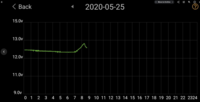
And a trace over the test period
B1A7A71B-7B3C-4835-A541-61406B1B8C05.jpeg

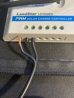
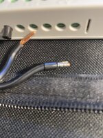
I was a bit unclear why it was just sitting at 12.7 ish volts so stopped the test just before 1PM and had a poke around at the panel and connections. I found a poorly crimped connection on the panel output so binned the crimp connector and tinned the cable end and remade the connection hoping this may be the issue. I restarted the test and left it for another couple of hours. Results were inconclusive.
440B20F0-3E7C-4362-B9EF-0648FEBBA9AF.jpeg8B3B4FCC-FF59-4930-8618-FE921E97258F.jpeg73FF91CD-B57C-46BB-847C-0DC50D39C867.jpeg

Remaking the connection didn’t really make any difference. Again it charged up to 12.7V and just stayed there. Below is the BM2 snapshot from the point I ended the test.
8CF0C9B3-A855-496B-A386-B4EDAD6335FB.jpeg

I’m not sure how to interpret this TBH. Part of me thinks the controller just went into float at 12.7V but the manual says that float is 13.1V. Another part of me wonders if the controller is just not great and another part of me wonders if the panel isn’t putting out enough voltage to allow the float voltage to be 13.1v.
It did charge the leisure battery which was the purpose of the test so from that POV its OK
@Dellmassive thoughts? What does your 50W BlueFusion panel provide as float voltage using the supplied controller?

Test 3 to follow when I get the bits to make up some connecting leads

E5BDB3E7-5C59-4071-8873-71A8634BA3A8.jpeg

D7A2A8F9-2528-4D1B-873F-E3B654EA35EA.jpeg

A4461256-C0EC-43C5-BEAB-A9258D6E7644.jpeg
 
Heres a link back to my results..


It looks like your leisure battery static voltage is around 12.2v by early morning.

It also looks like the controller is sitting in float mode, is the battery already charged,?

The float is around 13.8v and boost around 14.4v.(but the battery will drag these levels down a bit as it takes a charge and current, only when the battery is higher in absorption will the voltage creep up to the 13.8v.)

Looks like your battery is sitting around 12.8v while charging .

Are you suffering from volt drop?

Is your 12v socket lead heavy gauge cable and not too long?


You can temp' test your ctek mppt with the crock clamps.... neg on body ground and the plus wire on the mppt input......(panel + direct to ctek and panel -ve to ground. Leave the PWM controller to the side for this)
 
Last edited:
Heres a link back to my results..

yeah, it looks like in your results the float level is around 13.1V, mine seems to be lower than that which is what is puzzling me


It looks like your leisure battery static voltage is around 12.2v by early morning.

It also looks like the controller is sitting in float mode, is the battery already charged,?
Yes that’s about right. My dashcam is connected to the leisure battery so draws down a little power from it overnight as does the voltage step down on the USB charger sockets.

I’m not sure about the float mode. I’d have expected that to be more like 13.1V than 12.8V. That’s the bit I’m puzzled by.

Looks like your battery is sitting around 12.8v while charging .
Agreed. I was expecting it to be more like 13.1V

Are you suffering from volt drop?

Is your 12v socket lead heavy gauge cable and not too long?
Honestly don’t know but I am using the exact same cable you are, the only difference being I have cut the end off, tinned the wires and inserted direct into the controller rather than splice as you have. In theory less volt drop than yours as there is no joint.....
I thought when i found the dodgy crimp connection that was the issue but appears it wasn’t.

You can temp' test your ctek mppt with the crock clamps.... neg on body ground and the plus wire on the mppt input......
I could do if i had any connectors to join the panel output cable to the crock clips cable ;) . I’ve ordered some Anderson PowerPoles and was planning to use the crock clip cable as the permanent solution. Chop the clips off and replace with a pair of power poles, same at the other end, a pair of power poles on the panel output and then two shorter pieces with powerpoles on one end, one from the CTEK and one from the PWM. I can then connect to either controller from the panel and have decent length of cable to place the panel on the roof or dash or screen. Using the clips first is a good suggestion though so once i get the connectors that’s what I’ll do
 
Connect up the panel again tomoz and post the BM2 reading......

I'll do the same to comparison.. (50w bluefusion)

As for the ctek, you can just use a bit of chock block for now.... 50w is only 3A max so there is no problem with a quick dodge to test out the setup.

Maybe also look at a 100w panel to add to your collection?. ... 150w could give you 9A (isc) possible charging current.
 
Todays test, back out with the BlueFusion 50W . . . . . and Leisure battery.

( @Big.mac )

Not looking good though with the weather =[

1590129050941.png

.20200522_063717.jpg

oh well.

todays setup. 50W Bluefusion.

20200522_062808.jpg

.

20200522_062841.jpg

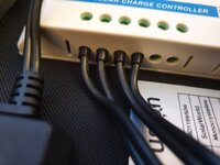
factory connections to PWM ...

20200522_062850.jpg

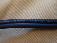
factory cable still fitted, a nice chunky 14AWG . . . .

20200522_063154.jpg

then I've added about 4ft of my own chunky cable to 12v plug . . . . 18AWG in this case . .

20200522_063236.jpg

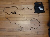
total cable is now . . . .

20200522_063352.jpg


which terminates at the fused plug . . .


20200522_063412.jpg20200522_063421.jpg


ill go for the top socket this time (leisure battery, currently the crappy OEM 70ah EFB+ VW offering)

20200522_063902.jpg

and panel on the roof, cable through window slit . . .


20200522_064046.jpg


cloudy day but the PWM is detecting a voltage from the panel, but will most likley have no current.


20200522_063925.jpg


the current state of the battery is via a BM2 readout 0630hrs :

Screenshot_20200522-063830_Battery Monitor.jpgScreenshot_20200522-063654_Battery Monitor.jpg


TBC later . . . . . . . . . .


1045hrs update . . . .

Screenshot_20200522-104723_Battery Monitor.jpgScreenshot_20200522-104409_Battery Monitor.jpg


TBC . . . . . . .

1215hrs . . . . .

disaster struck . . . . its getting a blowy outside and a gust of wind has just thrown the panel flying to the floor, ripped the controller out and everything...

But it looks like its survived . .

Now back on the roof and stuck down with some surface magnets and reconnected to the van.

20200522_121652.jpg20200522_121656.jpg


power wise, we are back on track . . .


Screenshot_20200522-122129_Battery Monitor.jpg


20 pic limit reached . .
 
Last edited:
Mine is out there too. I decided to bin the cigarette socket, put the crock clips back onto the controller and connect straight to the battery. That way any losses in the cable or wiring in the van are eliminated.

Weather here is much the same as London :( but there is a little sun breaking through the clouds occasionally.
B127A23C-967B-441A-8D63-D74DDAF9D550.png

I also noticed that my cigarette lighter cable is different to yours despite ordering using the link you provided to Amazon. It’s still a decent sized cable at 1mm sq. slightly heavier than your 18AWG cable but not as chunky as the 14AWG that comes with it and has the clips on. Anyways the cable is ruled out as I’m not using it.
BD32ADF9-EAB8-40C1-B225-D2F254720476.jpeg

I connected up around 9.30AM and despite there being no sun at that time I immediately saw a little charge so we’ll see how it goes today....

BM2 snapshot from just before connecting:
8BBD6607-CBAB-4E8D-9C3A-80382302B483.jpeg

And at 11:20
44986852-D04F-487B-B0F1-5E1ACD39EBDC.jpeg362536F7-1356-4DDB-B64F-792244DF47F4.jpeg

So far so good and in overcast conditions.....

Updates to follow.............
 
No idea why, but I seemed to post this in the wrong thread, so I’ll try again!

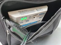
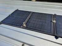
In order to try and extend my time ‘off grid’ I wanted a quick and simple mobile solar solution. I went for a 50w folding solar panel with regulator from Bluefusion. It’s a PWM regulator and has a USB out port.

It was listed at £92 on eBay, but they had a savings code, and it came in at £85. As per @Dellmassive , it’s normally about £2 per watt, so at £85, it was a good buy.

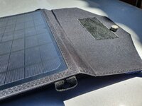
It’s amazingly small and light. Not a lot bigger than a couple of magazines stacked up.

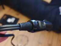
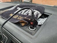
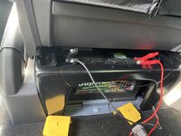
It’s fitted with insulated croc clips, but I’ve changed this for a fused (fuse is IMPORTANT) cigarette plug so I can plug it into the sockets for the leisure or starter battery.

Fits nicely on the dash, or on the windscreen for maximum gain. I can actually fit my internal blind, and the panel will still see the sky.

You can see from the BM2 read out that the voltage spiked up to 13.9v about 10:30am (no load on the battery). I put the fridge on (72w compressor fridge) at about 10:45am and it was warm, so had to work hard. Voltage dipped to 12.6v under load. When the fridge was cool, the compressor turned off, and the voltage crept up to 13.v and back to 12.6v when the compressor was on.

Under good sunlight, it seemed to be keeping up with the fridge. I unplugged the solar panel at about 13:30, and left the fridge on, and you can see a downward trajectory on the graph as the battery drained.

I’ll get an ammeter on it at some point, but overall really pleased for a simple, cheap and quick solution.

PS, I know it desperately needs a wash!

View attachment 70357

View attachment 70358

View attachment 70359

View attachment 70360

View attachment 70361

View attachment 70362

View attachment 70363

@Spaghettiboy78 are you able to join in this 50w BlueFusion test today at all?

dash mount or other?
 
Mine is out there too. I decided to bin the cigarette socket, put the crock clips back onto the controller and connect straight to the battery. That way any losses in the cable or wiring in the van are eliminated.

Weather here is much the same as London :( but there is a little sun breaking through the clouds occasionally.
View attachment 70883

I also noticed that my cigarette lighter cable is different to yours despite ordering using the link you provided to Amazon. It’s still a decent sized cable at 1mm sq. slightly heavier than your 18AWG cable but not as chunky as the 14AWG that comes with it and has the clips on. Anyways the cable is ruled out as I’m not using it.
View attachment 70887

I connected up around 9.30AM and despite there being no sun at that time I immediately saw a little charge so we’ll see how it goes today....

BM2 snapshot from just before connecting:
View attachment 70888

And at 11:20
View attachment 70889View attachment 70890

So far so good and in overcast conditions.....

Updates to follow.............
Today’s results were much better than yesterdays despite there being less sunshine.
As per post above I binned the cigarette lighter cable and went back to the croc clips and attached directly to the leisure battery.
The battery started showing an increase in voltage almost immediately even though it was overcast and once it was up over 13v I think the controller switched to float mode. I could see the voltage vary a little from 13.1ish when overcast up to 13.8V when the sun was shining. This is much more in line with what I was expecting so I’m pretty pleased with todays test.

Next question is what caused yesterdays problems?
panel too hot - it was way way hotter than today
high resistance connection somewhere either in the cable or in the van wiring between socket and battery?

Here’s a trace showing the days charging.
26C3193A-E483-48E8-8FFA-DA42379E2B99.jpeg

And this I think is the highest it reached:
64718844-D197-4052-905B-D3758B987840.jpeg

And after i ended the test with the panel removed:
437808B3-5B50-4560-93BF-8293787B4A13.jpeg

And just for fun, showing how I connected it up:
842A7CB1-B5C4-4BDF-B3FC-E87ABDC31B04.jpeg

And while all this was going on I went and bought myself some wheels so I’ll be a very happy bunny when I pick them up over the weekend sometime......

I still plan to do the test using the CTEK MPPT controller so will add that at a future date.
 
Today’s results were much better than yesterdays despite there being less sunshine.
As per post above I binned the cigarette lighter cable and went back to the croc clips and attached directly to the leisure battery.
The battery started showing an increase in voltage almost immediately even though it was overcast and once it was up over 13v I think the controller switched to float mode. I could see the voltage vary a little from 13.1ish when overcast up to 13.8V when the sun was shining. This is much more in line with what I was expecting so I’m pretty pleased with todays test.

Next question is what caused yesterdays problems?
panel too hot - it was way way hotter than today
high resistance connection somewhere either in the cable or in the van wiring between socket and battery?

Here’s a trace showing the days charging.
View attachment 70936

And this I think is the highest it reached:
View attachment 70937

And after i ended the test with the panel removed:
View attachment 70938

And just for fun, showing how I connected it up:
View attachment 70939

And while all this was going on I went and bought myself some wheels so I’ll be a very happy bunny when I pick them up over the weekend sometime......

I still plan to do the test using the CTEK MPPT controller so will add that at a future date.
Good test. Process of elimination now....

Looking forwards to your ctek test.. =)
 
Update. The panel was in the sun (outside of windscreen) up until about 2:30 then the sun went behind the van and then charge dropped off. I deliberately left it there to get an ‘honest’ test without chasing the sun. Current waved between 1.65a and down to 300mA.

753A082C-5DD7-4B58-BC02-66BF9B46456D.png
 
After earliers disaster with the wind . . .

We was back on track....

Here today's readout.

Panel on roof as per previous.

Screenshot_20200522-204043_Battery Monitor.jpgScreenshot_20200522-204029_Battery Monitor.jpg


...


The chart shows bulk charge to 14.4v.

Then float to 13.2v . . . . .
 
Today's test will be a continuation from yesterday.

but this time the panel moved to the inside dash. . . . 50W Bluefusion, and plugged into the 12v socket for the Starter battery. (Lwr dash socket)

The front windscreen is shaded by the house and a tree . . . . . . . lets see what happens.

today forecast:

Warm, Windy, Medium UV.

1590216472088.png


this is what we have so far:

Screenshot_20200523-075316_Battery Monitor.jpgScreenshot_20200523-075106_Battery Monitor.jpg


edit: next day review.

here are the results and as to be expected.

Screenshot_20200524-075443_Battery Monitor.jpg


Screenshot_20200524-075455_Battery Monitor.jpg


due to the house and tree blocking the solar and view of the sky the solar yield was very low.
to the point that the starter battery never reached the 13.0v trigger voltage of the Redarc DC-DC . . . .

which means that the starter battery did not get any "Auto VSR" charge yesterday.


which can be seen here . . . . . No secondary charging occurred . .


so effectively we had a marginal trickle charge that has counteracted any self discharge and a very slight increase on SOC over the day.


Screenshot_20200523-204416_Battery Monitor.jpg


Screenshot_20200523-204426_Battery Monitor.jpg

edit:

the panel is still on the dash (facing house and tree so shaded most of time)

heres the next day . . .


1590394823052.png

.

1590394844166.png

.

1590394861482.png
 
Last edited:
  • Like
Reactions: mmi
Test number 3 completed today.
This was with the Bluefusion 50W panel connected directly the the CTEK250SE installed in my van, not using the controller that was supplied with the solar panels.

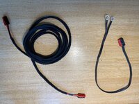
To start with I had to make up some cables as follows:
  1. I cut the cable between the solar panel and the solar controller supplied with it and inserted a pair of powerpole connectors on each of the cut ends
  2. I made a new extension cable from 14AWG red/black and terminated each end in a pair of powerpole connectors
  3. I made a short cable from 14AWG cable terminated in a pair of powerpole connectors on one end and M8 eyelets on the other. This connects to the CTEK
This enables me to connect the original controller to the panels or to disconnect the original controller and connect via the extension cable to the CTEK, thus giving me the flexibility to connect to other stuff if i need to (e.g. direct to the Starter battery or to one of my motorcycle batteries).

The cables look like this:
DCFF6DBE-CDCF-4DED-B1B9-CC436406B94B.jpeg

Connected to the original controller:
2A2D0680-8EA2-4B13-9DB9-EB640ED46679.jpeg

Bypassing the original controller:
D7A6525E-DEFB-478B-B2B4-83B5C4D47D54.jpeg

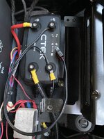
And the short connector added to the CTEK: I then just poked the connector through so it is easily accessible from under the front of the drivers seat.
2AA26DF9-0014-4484-8DF8-0F2A8DAC1852.jpeg

So with the cabling made up I started the test in the same way as the previous two.
I connected the panel a little before 7AM this morning and laid it on the roof. At this time there is no sun on the van.

BM2 reading from before connecting up:
E349B6AC-F25A-4588-A465-783BBA5F54E8.jpeg

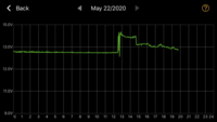
The sun gets on to the van around 9.30AM. You will see in the trace below that there was a very small charge up until around 9.30 and from then it increased significantly and continued to climb pretty much all day. This looks much less peaky than the two previous tests. I moved the panel onto the front of the van up against the windscreen but I can’t remember exactly when. I think it was where the slight dip is at 14:30ish. It was obviously catching more light from then on as the graph gets a little steeper.
Unfortunately I had to go out in the van at 3PM hence the test ending then. I’d have like to have got to the point where the CTEK started to trickle charge the starter battery but I didn’t get that far.
9D35CC44-BBC1-4782-BE11-428EADF0C1F1.jpeg

At 3PM I took my dog for a walk on the beach (I live very close). While I was there I thought I’d stick the panel on again but this time inside the windscreen. Later in the day, laid flatter and behind the glass so probably not the optimal setup but worth a go and a rel life situation. This is the trace extended to include that period. The two high peaks are the drive there and the drive back, the flat section where it is around 13.5V is the period the panel was connected up in this way:
C1631E1C-AC0D-4B54-A7BA-EEA726BC12F4.jpeg

As I said, I’d like to have got to the point where the CTEK started to trickle charge the starter battery but other than that I am very pleased with the results.
I set out to test whether a cheapish portable solar panel would be capable of charging starter or leisure batteries for periods where the van is not in use or whilst remote and parked up. I’m happy that it will do this given decent sunshine. What I have learned is that the CTEK appears to be the better way of charging the leisure battery. I’d like to test the reverse charge of the starter battery but will need to find a suitable window where I can leave the van for longer to do this. A higher output panel would obviously do this more quickly but i think for my personal needs what I have works.
 
Good test, . . . well done.

Remember the panels included controller is a cheapish PWM controller . . (Witch effectively just switches the panel volts to the battery very quickly to moderate the mean average)

The ctek has an internal mppt controller which is more efficient.

The average trend is 3A on 50w panel. And 6A on a 100w panel. (Max in full sun ISC rate etc)
 
At 3PM I took my dog for a walk on the beach (I live very close). While I was there I thought I’d stick the panel on again but this time inside the windscreen. Later in the day, laid flatter and behind the glass so probably not the optimal setup but worth a go and a rel life situation. This is the trace extended to include that period. The two high peaks are the drive there and the drive back, the flat section where it is around 13.5V is the period the panel was connected up in this way:
View attachment 71901
Hi @Big.mac, thanks for the tests.

Have I read that correctly in that the only time you had the solar panel inside the van (behind the windscreen, on the dashboard), it wasn't really providing any power (the voltage on the trace remains constant? This is how I was intending to use this panel if I bought one, so doesn't seem like a great result. Do you think there were other factors affecting this?

Also, how is the original controller fixed to the solar panel? Is it removable?
 
Hi @Big.mac, thanks for the tests.

Have I read that correctly in that the only time you had the solar panel inside the van (behind the windscreen, on the dashboard), it wasn't really providing any power (the voltage on the trace remains constant? This is how I was intending to use this panel if I bought one, so doesn't seem like a great result. Do you think there were other factors affecting this?
No I don’t believe that is right. While the panel was on the inside of the screen on the dashboard it was providing an output of 13.5V. By this time the battery was already pretty well fully charged so I suspect the CTEK went into float mode which will hold the output voltage a little lower. You can see when the panel was disconnected the battery voltage is actually a little lower than this at just below 13V. It was also later in the day and the panel was not angled towards the sun. Putting on the outside off the screen at an angle towards the sun would potentially have increased the output (if the CTEK was not in float mode) but it was certainly working on the dashboard.

This is exactly how I will likely use it most often. I may do another test with it like this sometime next week. I’ll also try and get an ammeter on it to show the output current. The problem for me is that where i park my van on the drive it doesn’t get any sun on the front until later in the day so the test will have to be shorter or I’ll need to park somewhere else.
The one thing for sure is that the MPPT controller on the CTEK is a better option than the supplied PWM controller.

Also, how is the original controller fixed to the solar panel? Is it removable?
It’s attached with Velcro to the case so easily removeable. The connections are screw terminals so also easily removed.
 
No I don’t believe that is right. While the panel was on the inside of the screen on the dashboard it was providing an output of 13.5V. By this time the battery was already pretty well fully charged so I suspect the CTEK went into float mode which will hold the output voltage a little lower. You can see when the panel was disconnected the battery voltage is actually a little lower than this at just below 13V. It was also later in the day and the panel was not angled towards the sun. Putting on the outside off the screen at an angle towards the sun would potentially have increased the output (if the CTEK was not in float mode) but it was certainly working on the dashboard.

This is exactly how I will likely use it most often. I may do another test with it like this sometime next week. I’ll also try and get an ammeter on it to show the output current. The problem for me is that where i park my van on the drive it doesn’t get any sun on the front until later in the day so the test will have to be shorter or I’ll need to park somewhere else.
The one thing for sure is that the MPPT controller on the CTEK is a better option than the supplied PWM controller.


It’s attached with Velcro to the case so easily removeable. The connections are screw terminals so also easily removed.
OK, yeah the charger in float mode makes sense. Sounds like you're intending to use it exactly as I plan to. Just trying to hold off spending yet more money on the van yet... Thanks!
 
OK, yeah the charger in float mode makes sense. Sounds like you're intending to use it exactly as I plan to. Just trying to hold off spending yet more money on the van yet... Thanks!
So I left the panels on the dashboard inside the screen most of today and the results are below.
I connected it up around 10:30, shortly after the two big peaks in the graph which were a trip to get my new wheels fitted :waving:
You can see a good steady charge until it gets to around 14v until it drops off around 17:00 to 13v. That is when the sun moved off the panel. The panel is still there and if i don’t need to use the van tomorrow I’ll leave it there all day tomorrow too. There will be some drain overnight as my dashcam is connected to the leisure battery and records in park mode.
Anyways, it shows the panel will charge pretty well even behind the glass.

8C91C8D4-8D05-4078-B0CB-12374EF6199C.jpeg

019DBA5F-C2E0-44FE-B657-994218902C7F.jpeg
 
Back
Top