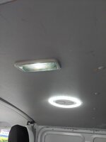
LED Interior Cargo Lights - How I Done It.

I've done something similar with an LED strip around my halo roof and have also replaced the courtesy lights with LED spots.
Both lighting systems are wired up via relays which are energised by an ignition on feed from the centre fusebox. For the spots with the ignition off the relay connects to the courtesy light circuit so they work as normal. With ignition on they switch over to a separate battery feed and can be manually switched on and off as required. The LED strip has a similar set up but with the ignition off it is isolated.
This way there is no risk of battery drain if a switch is left on. When I eventually fit my leisure battery I will power the "ignition on" side from this instead.
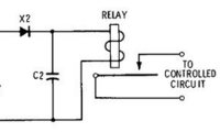
If you search "DPDT" there are lots of threads concerning interior lighting circuits. DPDT (double pole, double throw) is the relay of choice for such installations.
 
After fitting a DPDT switch to sort the roof lights, what is the most elegant solution to sort out the door step light?

I also think I must be a bit thick as I’ve looked through this thread and cannot fathom the advantage of using a relay instead of a switch? What is the benefit of using the relay?
 
What do you want the step light to do?

The main advantage and essentially the reason for using relays or contractors is that they isolate the power supplies from a switching circuit. This may not be such an issue when everything is 12v but it can enable us to switch higher current circuits through a typically lower current rated switch.

With the interior lighting circuit there's is no common earth in a typical sense. As @Dellmassive states in post# 1 you'll have either;

"Factory Non-LED 3 wire setup:

(brown) - earth point left a-pilar
(brown/red) - connection 1 main harness (BCM switched neg 0v)
(red/black) - positive connection 1 main harness (BCM timed +12v) ( 7.5A fuse 24 holder C)
****************************************************************************************

Factory LED 2 wire setup:

(brown/red) - connection 1 main harness (BCM switched neg)
(red/black) - positive connection 1 main harness (BCM timed +12v)( 7.5A fuse 19 holder C)"

To incorporate the original functions of the interior lighting circuit (door open on and timed off) with any additional manually switched circuits you would need to be able to switch multiple sources through one switch. This is both impractical (lots of wires to and from) and not really possible with the range of switches typically used in our vans. With one or more relays utilising multiple poles this can all be achieved via a single tiny switch while keeping the majority of wiring together in a separate dedicated area.
There is also the possibility of electrically switching the relay via an ignition on signal/12v supply so that one or more circuits can be automatically turned on or off when the van key is turned.
Thanks for taking so much time to explain the relay functionality. I understand this and it all makes complete sense to me and in the case of the 3 wire, but with the 2 wire setup it seems unnecessary to use relays unless your wanting to switch via ignition, switch something with a high current or do something else which I don't understand.

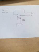
The below set up looks really really simple and that is worrying because this usually means I am about to cause something to catch fire!
1616148765996.png
Obviously, the selected DPDT switch will ne ON-OFF-ON so ensure that lights can be fully turned off but I would like to disable the doorstep light when the lights are switched to the leisure battery position. I wondered what other people have done to make the door step light go out when required.
 
The DPDT is ON-ON. The only way to achieve an OFF position is by only using one side, essentially making it single pole ie. ON-OFF or OFF-ON. What you have above would allow the leisure battery to be left on assuming there is no other main switch. This isnt ideal but I don't know how the LB supply is controlled.
I think a relay energised by the leisure battery supply would do exactly what you need. This would remove the need for a dedicated switch purely for the step. Something like this would do it as an example.
No doubt there are other ways to achieve this.16161548435618951185992838997965.jpg
 
Hi forum (this is my first post),

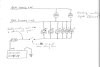
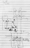
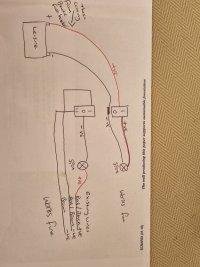
I am currently fitting a set of 6 LEDs to the back of my Kombi. After reading through this thread, I think I understand how to wire them up to do what I want, but I've attached my circuit here for feedback please.

Basically, I'm happy leaving the existing 3-wire filament courtesy lights in as courtesy lights that come on when the door is opened, and then time-out. So the new lights, I don't need them to come on when the door is opened, only when they are switched on. However, I would like them to go off when the van is locked, or when the engine is started, in case they've been forgetten to be switched off. Basically, I want lighting available from the switch whenever anyone could be in the van, but not driving it.

So I think that all I need to do is wire the new lights to fused +ve from the leisure battery (so they don't ever time out) via the wall switch, and BCM -ve so that they go off when the van is locked or driven. Is this correct, is BCM -ve always available apart from when locked and driving? Where is the best place to pick up BCM -ve, I thinking my choices are either to splice in at the existing courtesy lights, or run back to the dash somewhere?

Also, from reading this thread I think I may need something else in the leisure battery +ve line to avoid either possible dim LED glow, or drain to/from starter and leisure battery, if the wall switch was left on. However, I think the circuit is safe to implement initially without this, given that this would only occur if the wall switch was left on, and the intended normal use is that the wall switch would be off except when lighting was needed.

So my question is, is there any reason this shouldn't work? And where is the best place to pick up BCM negative?

(the existing lights are 3-wire BTW, but I've left off the rocker switch function and earth from the diagram to keep it simple)

MyLightingCircuit.png
 
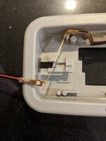
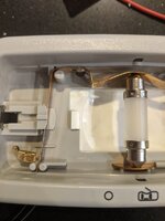
I'm going the relay route, but have adapted the rocker switch lights so I can use them to override the relays at night in the back of the van:
PXL_20210424_194641113.jpg
PXL_20210424_195200453.jpg
Using this feed wired to a relay I have control when we need to keep the leisure lights off in the nighttime if we open a door
 
I've fitted a light running off a relay but I have an annoying problem that the relay chatters as the main lighting fades on. Is there an easy fix to this? I'm thinking whether the fading is a setting I can switch off in the ecu?
 
Could try something simple like e.g.
1619506712242.png
Depending on relay coil resistance some experimenting with capacitor value needed. It's 200Hz PWM feeding the relay...
Certainly more sophisticated solution would be the BCM tweak... possibly in uncharted adaptations.
 
Could try something simple like e.g.
View attachment 113894
Depending on relay coil resistance some experimenting with capacitor value needed. It's 200Hz PWM feeding the relay...
Certainly more sophisticated solution would be the BCM tweak... possibly in uncharted adaptations.
Perhaps it's the PWM causing the chatter, per your other analysis. It's more a buzz/whine, not a chatter, thinking about it
 
  • Like
Reactions: mmi
@mmi @Robert I need to check whether PWM can be suppressed on the courtesy lighting, do you happen to know?

Here's my setup...the rocker light is on the courtesy 12V circuit and drives the cool white side of the leisure ring light which is a separate 5V USB circuit. The relay works perfectly, and the rocker allows me to switch off the lighting at night (and hence the relay activation), but the relay whines with the fade up and fade down.

The ring light then has separate control of a cool white, warm white, or combined output and dimming settings, so can be almost a night light when needed in the middle of the night.
PXL_20210427_080808594.jpg
PXL_20210427_083701403.jpg
 
Last edited:
  • Like
Reactions: mmi
It's probably buried in this thread somewhere, but here again is an alternative to a relay. Cost is not much more, and it will allow your extra lights to fade up and down as with the normal courtesy lights but without the chatter you get with a relay.
 

Attachments

  • Simple Courtesy Light Switching.pdf
    102.9 KB · Views: 70
@mmi @Robert I need to check whether PWM can be suppressed on the courtesy lighting, do you happen to know?

Here's my setup...the rocker light is on the courtesy 12V circuit and drives the cool white side of the leisure ring light which is a separate 5V USB circuit. The relay works perfectly, and the rocker allows me to switch off the lighting at night (and hence the relay activation), but the relay whines with the fade up and fade down.

The ring light then has separate control of a cool white, warm white, or combined output and dimming settings, so can be almost a night light when needed in the middle of the night.
View attachment 113899
View attachment 113900
Not verified but have you tried this?

 
  • Like
Reactions: mmi
I haven't measured interior lights voltage,
maybe @mmi have.
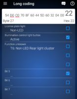
And there seems to be only one bit in the BCM
which could be related (Byte 27 bit 1).
That shows as license plate for me on OBD11:
Screenshot_20210428-085349.png

Just looking around now

Edit: oops, that bit 0
 
Last edited:
On my MY18 T6 (PV) BCM 7E0937090C byte 27 bit 1 set to "0" has no effect on interior light on/off dimming. Instead, it turns off dash button lights and disables instrument light dimming (stays on full).

Test setup: ignition off, parking (side) lights on, thus instuments and dash buttons are illuminated and controlled by dimmer. No ignition cycling between coding changes - the effects were seen upon change.
 
Hmm.. I'm happy to play around so long as we think there's a setting there somewhere. Any other clues as to where to try? I've looked through all the OBD11 descriptions. Can someone check a VCDS for interior light fade or dimming?

Ross tech on the T5 Transporter T5 GP & BCM, problems with long code helper
Byte 27 Bit 0 License plate light in LED design (Kennzeichenbeleuchtung in LED Ausführung)

Byte 27 Bit 1 Activation terminal 58d active via Body Control Module (BCM) with pulse width modulation (PWM) (Ansteuerung Klemme 58d über Body Control Module (BCM) mit Pulsweitenmodulation (PWM) aktiv)

And @mmi you've been here before!
As @Deaky above. Instrument lights have their own auto functionality of dimming. Not really related to auto driving lights. The same can be seen also on other VAG platforms.


Can be verified by having the van in the dark, turning driving lights off (0), ignition on, doors closed, etc. Illumination of speedo and rev counter will fade out in a few seconds (if even on at that point anymore). The info display in between will stay somewhat illuminated, and so readable.


Have a torch and give good light to instruments (probably more on rev counter side (on LHD)) and speedo and rev counter should light up. And starts to fade away. When driving you will see the same when entering a deep shadow like a tunnel – lighting of intruments gradually dim, and brighten up when back in bright.


There are some configuration possibilities available how lighting works, at least in DRL portion of it. The above is how mine came from factory. I think the purpose of this functionality is a kind of driving light reminder – when driving lights are switched off.
 
Last edited:
  • Like
Reactions: mmi
so on yours the BCM must switch the relay on for the +v timer and use the BCM -v for the fade-out. (so i assume when you take the relay out you loose all the internal lights?)
Could this be helpful, if I take a -ve from elsewhere. Can anyone check this assertion?
 
I can corroborate this. The courtesy lights in the rear have three lines. A gnd brown, a switched +ve red/blk, and switched -ve brown/red.

When the rocker light is in the "on door opening" position, the lights fade on and off when you unlock the van or open a door. And the lights fade off when the time out is reached or after closing the doors. When the rocker light is in the "stay on" position the light does not fade on/off when you unlock the van, or when it times out, but ignores the door opening. So it's the switched -ve that does the fade.

Hence, when the relay is connected between the switched +ve and switched gnd, the relay chatters/buzzes. When the relay is connected between the +ve and the gnd it does not, but the relay stays switched all the time when unlocked, ignoring the doors.

So we'd be looking for a door opening fade, not an interior light fade, in the settings.
 
Last edited:
  • Like
Reactions: mmi
Now I've got a weird behaviour again. With the relays connected in parallel with the interior rear rocker lights (using an LED Osram bulb) the front cab lights stay on half brightness after I start the engine. I mean wtf!? If I switch off the rockers in the back the cab lights go off fully. But not 100% on this behaviour yet, I only noticed today.

P.S the front cab lights are led too, so don't dim. Must be pwm
 
Back
Top