I know it's a daft question but you have fitted a new MFSW / Airbag loom?Totally stuck mfsw all wiring connected
Steering wheel connector wires added to pin 9 & 10 connected to the blue/green cable on the bcm and 12 volt from the light switch.
Nothing working on the wheel would of thought the buttons would of at least illuminated though the light switch
Van is a euro 6 so bcm connection is correct
Any help anyone getting to the point of refitting my old wheel and selling the new one (wheel was bought from t5upgrades so I know it fits
You are using an out of date browser. It may not display this or other websites correctly.
You should upgrade or use an alternative browser.
You should upgrade or use an alternative browser.
MFSW - Golf GTd MkVII + DSG Paddles -- How I Done It --
- Thread starter Dellmassive
- Start date
Mark72
Member
Yeah the steering wheel air bag came with all the wiring to the buttons all I added was the two cables to pin 9. & 10I know it's a daft question but you have fitted a new MFSW / Airbag loom?
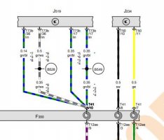
Euro 6, according to the wiring diagrams should be pin 36 grey/white cable look at *8
Check you've connected to the correct cable behind the switch
Have you coded it?
Buttons only light up when the lights are on so they're switched by the light switch they're done by canbus so if you've not coded the wheel or connected to the correct lin cable then this might be why they don't work.


Check you've connected to the correct cable behind the switch
Have you coded it?
Buttons only light up when the lights are on so they're switched by the light switch they're done by canbus so if you've not coded the wheel or connected to the correct lin cable then this might be why they don't work.


Mark72
Member
Thanks I'll try pin 36 on the bcm hopefully that's my problemEuro 6, according to the wiring diagrams should be pin 36 grey/white cable look at *8
Check you've connected to the correct cable behind the switch
Have you coded it?
Buttons only light up when the lights are on so they're switched by the light switch they're done by canbus so if you've not coded the wheel or connected to the correct lin cable then this might be why they don't work.
View attachment 129058
View attachment 129059
I've coded the wheel using OBDeleven which was easy
I connected to the black cable on the light switch which is 12volt
Thanks for the help
Mark72
Member
Is this still in the white bcmEuro 6, according to the wiring diagrams should be pin 36 grey/white cable look at *8
Check you've connected to the correct cable behind the switch
Have you coded it?
Buttons only light up when the lights are on so they're switched by the light switch they're done by canbus so if you've not coded the wheel or connected to the correct lin cable then this might be why they don't work.
View attachment 129058
View attachment 129059
Mark72
Member
There's no grey and white cable there only a green and greyIs this still in the white bcm
I dunno then mate, speak to the place you got the wheel fromThere's no grey and white cable there only a green and grey
Mark72
Member
I opened up the connector on the bcm found the grey/white cable connected to that still nothing, will check the light switch connection is correct I connected to the black cable which is showing 12volt , next I'll need to remove the steering wheel and check the voltage there, thanks
Interesting as I am looking at theirs for my 6.1 I will hold off. Is it a case of programming via vcds?Totally stuck mfsw all wiring connected
Steering wheel connector wires added to pin 9 & 10 connected to the blue/green cable on the bcm and 12 volt from the light switch.
Nothing working on the wheel would of thought the buttons would of at least illuminated though the light switch
Van is a euro 6 so bcm connection is correct
Any help anyone getting to the point of refitting my old wheel and selling the new one (wheel was bought from t5upgrades so I know it fits
Mark72
Member
I've coded mine using OBDeleven easy to do and it's saying code accepted, going to test the steering wheel wires sure I'll get it working. My van didn't have a mfsw be so I had to add in two cable from the column connector bit of a pain of a job but everyone does itInteresting as I am looking at theirs for my 6.1 I will hold off. Is it a case of programming via vcds?
Mark72
Member
Yeah got it sorted thanks I had used a scotch lock on the bcm bad connection wires soldered and all works@Mark72 did you get this sorted in the end? I've got the same setup as you so assumed a wheel from T5 Upgrades (with the two relevant patch wires, airbag loom, correct buttons etc) plus some coding would be job done but sounds like you've had issues..?
ok, so you spliced into pin 36 on the BCM in the end (rather than 17) using the scotch lock from pin 10 on the steering wheel? Then pin 9 spliced into to the feed from the lights?
Ah ok, yeh those scotch locks don't have a good reputation. I had to use them on my towbar because it was impossible to crimp or solder into the BCM cables so fingers crossed they stand the test of time. Thanks for your feedback
Mark72
Member
Thanks for the helpAh ok, yeh those scotch locks don't have a good reputation. I had to use them on my towbar because it was impossible to crimp or solder into the BCM cables so fingers crossed they stand the test of time. Thanks for your feedback
HiPage 2 held.
View attachment 29658
.
View attachment 29659
.
View attachment 29660
.
View attachment 29661
.
View attachment 29662
.
Edit:
1.9 Multifunction steering wheel control unit -J453-
1.9.1 Fitting location:
in steering wheel
A - Multifunction steering wheel control unit -J453-
A1 - 5-pin connector -T5u- , black
View attachment 39627
...
View attachment 39628
Cruise control system switch (J453), Multifunction buttons on left in
steering wheel, Brake light switch, Coil connector, Clutch
position sender, connects to the (J623 Engine/motor control unit, in E-box in engine compartment) Engine/motor control unit, Mechatronic unitfor dual clutch gearbox via the ClockSpring - F350 Coil connector, in steering wheel.
*******************************************
Multifunction buttons on left in steering wheel (E440) , Coil
connector (F350), Alarm horn, Driver door control unit, Front
passenger door control unit, conect to the Onboard supply control unit (J519)
View attachment 39629
...........................
Multifunction buttons on left in steering wheel, Multifunction
buttons on right in steering wheel, Coil connector, Airbag
control unit, Multifunction steering wheel control unit,
Onboard supply control unit
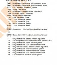
E440 Multifunction buttons on left in steering wheel
E441 Multifunction buttons on right in steering wheel
F350 Coil connector, in steering wheel
J234 Airbag control unit
J453 Multifunction steering wheel control unit
J519 Onboard supply control unit
N95 Driver side airbag igniter
T5u 5-pin connector, black
T12ae 12-pin connector, yellow
T41 41-pin connector, grey
T50 50-pin connector, yellow
T73b 73-pin connector, white
B528 Connection 1 (LIN bus) in main wiring harness
B549 Connection 2 (LIN bus) in main wiring harness
View attachment 39630
.
View attachment 39631
***************************
E441 RHS Multifunction buttons on right in steering wheel connects to > E440 Multifunction buttons on left in steering wheel (via ribbon cable)
E440 LHS buttons are on J453 Multifunction steering wheel control unit.
J453 connects (via LIN bus T5u/3 0.35mm purple/white)via the F350 slip ring to the BCM (J519)
J453 connects (T5u/5 0.35mm grey) via the F350 slip ring to the (J623) Engine control unit
12v power (T5u/2 0.35mm white) via > SC32 Fuse 32 on fuse holder C to (F350 to J453)
0v ground (T5u/1 0.35mm Brown)(Earth connection, in airbag wiring harness )via > F350 > Earth point, onboard supply control unit
Horn plate feed to J453 (T5u/1 0.35mm blue/white)
Horn plate ground (T5u/1 0.35mm Brown)(Earth connection, in airbag wiring harness )
so there should be 6x wires at the yellow connector, 2x for Airbag and 4x for power and data)
no illumination feed from what i can see, so the switch modules must get the illumination PVM via the LIN Bus.
****************************
airbag N95
2cores - black/green via F350 slipring to J234 Airbag control unit
****************************
So the CC buttons effectivly talk to the ECU
and
the RHS buttons talk to the BCM via LIN bus for the MFD, phone, radio buttons.
these are readout from INSTRUMENTS.
View attachment 39635
.
and CC buttons here >
View attachment 39638
*****************************************
LIN Bus Explained - A Simple Intro
*****************************************
.
More info over here > Dellmassive`s -- "how I Done It" -- Thread
.
Hi, I’ve have been chasing my tail for a while now which this. I have a start line with the same wheel as you, have done exactly the same as you and nothing works. The lights do work on the wheel but it ends there. Did you change your BCM or your clock spring? I’ve noticed on mine pin 11 on the T41 connector for the stalks which is supposed to be for the ACC the pin isn’t there . Not sure if a high line clock spring has this in place ???Page 2 held.
View attachment 29658
.
View attachment 29659
.
View attachment 29660
.
View attachment 29661
.
View attachment 29662
.
Edit:
1.9 Multifunction steering wheel control unit -J453-
1.9.1 Fitting location:
in steering wheel
A - Multifunction steering wheel control unit -J453-
A1 - 5-pin connector -T5u- , black
View attachment 39627
...
View attachment 39628
Cruise control system switch (J453), Multifunction buttons on left in
steering wheel, Brake light switch, Coil connector, Clutch
position sender, connects to the (J623 Engine/motor control unit, in E-box in engine compartment) Engine/motor control unit, Mechatronic unitfor dual clutch gearbox via the ClockSpring - F350 Coil connector, in steering wheel.
*******************************************
Multifunction buttons on left in steering wheel (E440) , Coil
connector (F350), Alarm horn, Driver door control unit, Front
passenger door control unit, conect to the Onboard supply control unit (J519)
View attachment 39629
...........................
Multifunction buttons on left in steering wheel, Multifunction
buttons on right in steering wheel, Coil connector, Airbag
control unit, Multifunction steering wheel control unit,
Onboard supply control unit
E440 Multifunction buttons on left in steering wheel
E441 Multifunction buttons on right in steering wheel
F350 Coil connector, in steering wheel
J234 Airbag control unit
J453 Multifunction steering wheel control unit
J519 Onboard supply control unit
N95 Driver side airbag igniter
T5u 5-pin connector, black
T12ae 12-pin connector, yellow
T41 41-pin connector, grey
T50 50-pin connector, yellow
T73b 73-pin connector, white
B528 Connection 1 (LIN bus) in main wiring harness
B549 Connection 2 (LIN bus) in main wiring harness
View attachment 39630
.
View attachment 39631
***************************
E441 RHS Multifunction buttons on right in steering wheel connects to > E440 Multifunction buttons on left in steering wheel (via ribbon cable)
E440 LHS buttons are on J453 Multifunction steering wheel control unit.
J453 connects (via LIN bus T5u/3 0.35mm purple/white)via the F350 slip ring to the BCM (J519)
J453 connects (T5u/5 0.35mm grey) via the F350 slip ring to the (J623) Engine control unit
12v power (T5u/2 0.35mm white) via > SC32 Fuse 32 on fuse holder C to (F350 to J453)
0v ground (T5u/1 0.35mm Brown)(Earth connection, in airbag wiring harness )via > F350 > Earth point, onboard supply control unit
Horn plate feed to J453 (T5u/1 0.35mm blue/white)
Horn plate ground (T5u/1 0.35mm Brown)(Earth connection, in airbag wiring harness )
so there should be 6x wires at the yellow connector, 2x for Airbag and 4x for power and data)
no illumination feed from what i can see, so the switch modules must get the illumination PVM via the LIN Bus.
****************************
airbag N95
2cores - black/green via F350 slipring to J234 Airbag control unit
****************************
So the CC buttons effectivly talk to the ECU
and
the RHS buttons talk to the BCM via LIN bus for the MFD, phone, radio buttons.
these are readout from INSTRUMENTS.
View attachment 39635
.
and CC buttons here >
View attachment 39638
*****************************************
LIN Bus Explained - A Simple Intro
*****************************************
.
More info over here > Dellmassive`s -- "how I Done It" -- Thread
.
just not qui sure as where to go from here.
I’ve checked that all the wires are in the correct location in their respective plugs and I know that I have 12 v and Earth to the wheel.
got a pic of what you have?Hi
Hi, I’ve have been chasing my tail for a while now which this. I have a start line with the same wheel as you, have done exactly the same as you and nothing works. The lights do work on the wheel but it ends there. Did you change your BCM or your clock spring? I’ve noticed on mine pin 11 on the T41 connector for the stalks which is supposed to be for the ACC the pin isn’t there . Not sure if a high line clock spring has this in place ???
just not qui sure as where to go from here.
I’ve checked that all the wires are in the correct location in their respective plugs and I know that I have 12 v and Earth to the wheel.
we needed to send off the Golf MFSW to have the IC Chips in the Golf button modules swapped out for T6 IC chips.
this was due to the Golf and T6 being on different platforms so the golf buttons wouldn't speak to the T6 modules.
when we had the wheel returned it was plug and play.
....
got a pic of what you have?
we needed to send off the Golf MFSW to have the IC Chips in the Golf button modules swapped out for T6 IC chips.
this was due to the Golf and T6 being on different platforms so the golf buttons wouldn't speak to the T6 modules.
when we had the wheel returned it was plug and play.
....

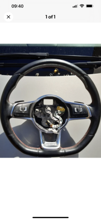
This is my wheel. I don’t have any chips from the old wheel as it wasn’t a MFSW ? Are your lights on the steering wheel white or red ?
Similar threads
- Replies
- 13
- Views
- 2K
- Replies
- 21
- Views
- 3K
- Replies
- 116
- Views
- 21K
