Orion 12/12/18 keeps switching off

As previously mentioned the “Battery Voltage” readings all look wrong. They should be virtually the same. Are all the outputs of the devices connected together very close to the smart shunt. The Orion & MPPT need connecting to the Smart shunt as close as possible with the same size & length of cable. Something is amiss currently (see what I did there?)
The shunt is on the negative and the other devices could (and probably are) connected to a vehicle ground near each box. Being close to the shunt on the negative side is irrelevant.

Cable sizes and length on the positive can be anything, so long as they don’t cause voltage drop or are too thin for the required power draw.

As an example, my DC-DC, shunt and LB are all under the passenger seat. My MPPT is in the rear wardrobe. The battery voltage is within 0.01v across all devices.
Yeah, so that isn’t the problem then cos again I’d have taken advise on gauges of wire from here
 
The shunt is on the negative and the other devices could (and probably are) connected to a vehicle ground near each box. Being close to the shunt on the negative side is irrelevant.

Cable sizes and length on the positive can be anything, so long as they don’t cause voltage drop or are too thin for the required power draw.

As an example, my DC-DC, shunt and LB are all under the passenger seat. My MPPT is in the rear wardrobe. The battery voltage is within 0.01v across all devices.
Yeah, my bad. Not having a smart shunt, I’d imagined it on the +ve side. The comment should be that all the sources should be close together on the +ve side. If there’s a discrepancy between the output voltages it can only be due to volt drop. If a device thinks it’s outputting XVolts at its terminal, but only YVolts are arriving at the battery, then the device will knock off thinking job done, but in reality there’s a drop somewhere & the battery is being short changed. We need to know what the LB battery terminal Voltage is compared to what the devices are (or think) they’re outputting. You can’t have 3 different voltages showing at a single point in the circuit.
 
And do k get this info from internal
Battery (fogstar) monitor. Or Victron app. Or by clever application of multi meter
 
Yeah, my bad. Not having a smart shunt, I’d imagined it on the +ve side. The comment should be that all the sources should be close together on the +ve side. If there’s a discrepancy between the output voltages it can only be due to volt drop. If a device thinks it’s outputting XVolts at its terminal, but only YVolts are arriving at the battery, then the device will knock off thinking job done, but in reality there’s a drop somewhere & the battery is being short changed. We need to know what the LB battery terminal Voltage is compared to what the devices are (or think) they’re outputting. You can’t have 3 different voltages showing at a single point in the circuit.
Yep, agreed but the differences seem to vary hence thinking it’s a connection issue rather than a cable sizing (hence voltage drop) issue.
 
I know I keep asking and it’s probably a naive question, would an auto engineer look at this and pretty simply find the problem or is this small fry for their attentions? I really don’t have much skill in these dark arts.
 
And do k get this info from internal
Battery (fogstar) monitor. Or Victron app. Or by clever application of multi meter
The Fogstar app will give you a good reading direct from the battery. Also, the multimeter direct across the battery terminals. That will give you a base line of what the LB voltage actually is.

You can then look to see what the other components think it is. A small (up to 3%) difference is fine but anything larger indicates an undersized cable or another issue such as a bad connection or crimp.

Checking each connection is physically tight is a good start. Also check there are no loose strands of cable at the connections into the Orion and MPPT (and any other similar bare cable connections). After that methodically work around the system checking voltages with the multimeter at each end of a cable. It should be near identical. I’m not sure why but I’d lean towards the negatives first.
 
I know I keep asking and it’s probably a naive question, would an auto engineer look at this and pretty simply find the problem or is this small fry for their attentions? I really don’t have much skill in these dark arts.
They would, but finding a reliable one that is prepared to take on, and understands, leisure electrics may be an issue. I’d do some simple checks as mentioned above first.
 
The Fogstar app will give you a good reading direct from the battery. Also, the multimeter direct across the battery terminals. That will give you a base line of what the LB voltage actually is.

You can then look to see what the other components think it is. A small (up to 3%) difference is fine but anything larger indicates an undersized cable or another issue such as a bad connection or crimp.

Checking each connection is physically tight is a good start. Also check there are no loose strands of cable at the connections into the Orion and MPPT (and any other similar bare cable connections). After that methodically work around the system checking voltages with the multimeter at each end of a cable. It should be near identical. I’m not sure why but I’d lean towards the negatives first.
Will make a start tomorrow. And it’s literally using multimeter probes on the 20 DC setting across wires yes. I’ll log all and post findings for comment. Thank you all again
 
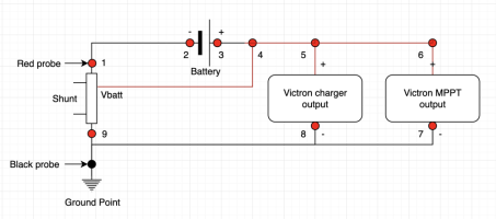
Here's a quick simplified wiring diagram of your setup (I hope). You likely have more elements such as fuses and maybe a bus bar but they can be ignored for the time being. With engine running and preferably charging on, try to measure and write down voltage between ground point (black dot) and each of the red dots in this wiring diagram:

1. Shunt battery side connection
2. Battery negative pole
3. Battery positive pole
4. The point where Vbatt feed to shunt connects to in positive wiring
5. The point where Victron charger output connects to in positive wiring
6. The point where Victron MPPT output connects to in positive wiring
7. Victron MPPT output negative terminal
8. Vicron charger negative terminal
9. Shunt chassis side connection

1734897475278.png

1, 2, 7, 8, 9 should read zero or very close to zero
3, 4, 5, 6 should read battery voltage or very close to it when charging is off, or higher when charging is on. They should also be very close to each other.
 
For each of these points do I just touch red probe to each numbered point and black to common negative point for a reading?
 
How do I do rear wardrobe stuff? Same again, positive to busbar and negative ti common negative rather than shunt etc
 
For each of these points do I just touch red probe to each numbered point and black to common negative point for a reading?
Yes. To make things easier you can attach black probe semipermanently to a common ground point eg by tightening it between couple of washers (as long as it gets good contact to the ground point). Then you only need to touch with red probe to make a measurement.


How do I do rear wardrobe stuff? Same again, positive to busbar and negative ti common negative rather than shunt etc
If you have some extra wire lying around make an extension lead for the probe - it does not need to be beautiful, just strip enough to wrap some copper around red probe, tape it and use the other end for measuring instead of the red probe.
 
Waiting for daylight. In mean time reposting this in case sheds any light.

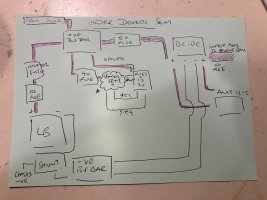
This is as I understand the system under the drivers seat. I will attempt the same for the rear wardrobe electrics too.

The cloud shaped middle of the page where it says ‘under seat ?’ With grey wires x2, a brown wire x1 and red wire x1 presumably communicates with rear wardrobe unit?68E2F3CE-176F-41ED-95A2-7E5C7C91803E.jpeg
 
Thanks.

I'm not sure if you need to care about wardrobe (leisure consumer) stuff too much at this point. You could even remove the 40A fuse until the main charging is rock solid just to rule out any and all possibility of anything there affecting measurements. Also it should be enough if you measure the MPPT return voltage from the bus bar terminal ring - we kind of already know what the MPPT thinks as it reports the voltage at it's positive output *terminal*, so 14.54V in the below picture - that's why I tried to instruct to measure little bit from other positions than from the actual Victron positive terminals.

So, these three voltages are measured at the terminals of the respective modules, they should be nearly same, and they all should connect to the bus bar or thereabouts.

1734942218578.png
 
Back
Top