Orion 12/12/18 keeps switching off

Here's a quick simplified wiring diagram of your setup (I hope). You likely have more elements such as fuses and maybe a bus bar but they can be ignored for the time being. With engine running and preferably charging on, try to measure and write down voltage between ground point (black dot) and each of the red dots in this wiring diagram:

1. Shunt battery side connection
2. Battery negative pole
3. Battery positive pole
4. The point where Vbatt feed to shunt connects to in positive wiring
5. The point where Victron charger output connects to in positive wiring
6. The point where Victron MPPT output connects to in positive wiring
7. Victron MPPT output negative terminal
8. Vicron charger negative terminal
9. Shunt chassis side connection

View attachment 268882

1, 2, 7, 8, 9 should read zero or very close to zero
3, 4, 5, 6 should read battery voltage or very close to it when charging is off, or higher when charging is on. They should also be very close to each other.
Ok here goes (very mindful some of positive busbar share terminal, so hopefully doesn’t foul results).

Across poles LB when off 13.28 when on 13.55

Across poles SB when off 12.37 when on 14.66

Shunt battery side connection 0.68

Battery -ve pole 0.54

Battery +ve 14.38

Shunt to +ve 13.42

Dc to dc +ve connection 14.3

Mppt +ve 13.8-14 (fluctuating)

Mppt -ve output (need to get into back of van)

Dc to dc - terminal 0.33 in one 0.41 in other

Shunt chassis side 0.33

Have to think about this a bit more but on a quick peek I would focus the investigation into the negative connections - shunt chassis side should be really really close to zero and 0.35V (0.68V - 0.33V) over the shunt sounds high as well.

(Nerd explanation: shunt resistances are very low, in the order of milliohm or so. Using ohms law I = V/R and plugging in above values we can see the current should be unrealistically high, somethings amiss)
I will continue tugging on connections (no euphemism) until someone comes back with any guidance as, as I promised, ‘I am out of my depth’
 
Found a little brown wire from under seat to negative bus bar was poor connection. I have remedied and these are numbers now?! Was that it!!!?

4A4D2BBE-725B-4334-BB33-0AFBC73170ED.png
 
Manipulating DC to DC and ‘heard some sparks’.

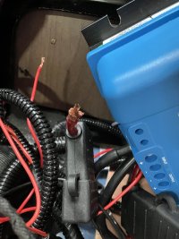
So investigating further the bigger red fused INPUT to dc to dc not a great connection.

With the little in line fuse holder so close under mechanical tension, should I ship this out and add a maxi fuse? Give myself more play?

And I HAD wired the engine live into Dc ti DC

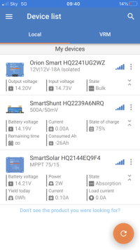
744E6D42-EB3D-4CFC-85B4-D357156839DA.jpeg
 
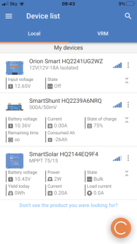
That was running engine. Some mad numbers with engine not running, have a fu**ed something?

7474FE1F-555F-4D91-908C-9B94EB9387BC.png
 
7FA300C5-1A17-4061-9C37-DCD4AA611F57.png

All off (engine) all numbers settled, presume just fried a bit with sparks?

All other connections seem solid

Is there consensus then numbers seem better?

Should I check at shunt again with multimeter to be sure
 
That looks much better. If the input connection to the DC-DC is still awkward you can remove that fuse entirely as it is not needed at that end of the cable. You only need one at the starter battery end. Remember, the fuse is to protect the cable and in this case there is no output from the input terminal of an Orion.
 
I’d also set the Orion auto detection back to default and see where you go from there.
 
Back
Top