A quick DIY way to test fuel lift pump's basic functionality.
The test takes advantage of engine's fuel high pressure sensor (in fuel rail). Running the lift pump continuosly makes the pressure eventually "leak" through high pressure pump and can be detected by fuel pressure sensor.
As a side product the test gives at least indication of fuel high pressure sensor's plausibility - the raw value (in Volts) and converted value (in kPa). However, as the pressure produced by lift pump barely reaches measurement range - for proper pressure measurement traditional means are still needed.
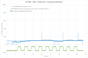
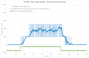
Below the green is lift pump activation (not scaled - just for timing).
Light blue sensor raw data (barely at low end resolution/sensitivity).
Dark/thick blue calculated sliding average of sensor data.
More than happy to create the plots - just attch the logfiles.
The test takes advantage of engine's fuel high pressure sensor (in fuel rail). Running the lift pump continuosly makes the pressure eventually "leak" through high pressure pump and can be detected by fuel pressure sensor.
As a side product the test gives at least indication of fuel high pressure sensor's plausibility - the raw value (in Volts) and converted value (in kPa). However, as the pressure produced by lift pump barely reaches measurement range - for proper pressure measurement traditional means are still needed.
HOW-TO Run engine's built-in test for Transfer fuel pump
IGNition ON
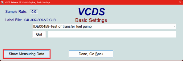
VCDS > Select > Engine > Basic Settings > IDE00459-Test of transfer fuel pump
Select "Show Measuring Data" (see below)

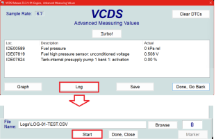
A selection window opens to tick the needed measurement data items
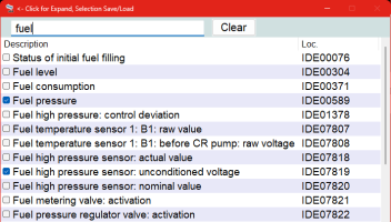
Find and tick the following:
- IDE00589 Fuel pressure
- IDE07819 Fuel high pressure sensor: unconditioned voltage
- IDE07824 Tank-internal presupply pump 1 bank 1: activation
Select "Log" (see below)
Select "Start"
Log for at least 30 seconds - to get "base level of presssure"

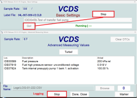
Start the test by clicking "Go" (below)
Let the test run for 90 seconds - then "Stop" (below top right)
Let the data logging still to continue for at least 60 seconds.

The log file is in folder C:\Ross-Tech\VCDS\Logs\....
Below the green is lift pump activation (not scaled - just for timing).
Light blue sensor raw data (barely at low end resolution/sensitivity).
Dark/thick blue calculated sliding average of sensor data.

More than happy to create the plots - just attch the logfiles.



 Just joking... probably just my pressure sensor calibration is bit higher as evidenced by the ripple even when lift pump was not on at all