Too Many OBDii Faults For My Liking!

While I’m waiting for my VDCS device to finish the coding of my starter battery i'm going to attempt to put together a shopping list for my leisure batteries, DC/DC charger and associated cables, fuses etc. It’s probably more than obvious from the rest of this thread that I could probably do with all the help I can get.

The van is already converted (list of components at bottom) so it is only the supply and distribution of the power I’m dealing with here.
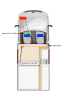
Attached is a basic sketch of my intended setup plus instructions for the CBE DS300 distribution board (already installed) and the Redarch BCDC1240D charger.

Shopping list:
Bosch LFD90 x 2
Redarc BCDC1240D B2B charger
Cables:
Twinflex: Starter battery to passenger seat 1600mm, Passenger to driver seat 900, Driver seat to dis board: 1000 = 3.5m (order 4m)
CBE DS300 back to starter battery (Single) 4 metres

Here are some things I could do with some help with:
1. Redarc recommend 60A fuse, I’m not inclined to go this high. What do others think?
2. Redarc's recommendation is 6 AWG up to 5 metre run and 4 AWG if unto 9 metres. Is 6 AWG (16mm2) enough or is there a benefit to going up to 4 AWG (25mm2)?
3. Is the earth best run all the way back to the battery Neg terminal as shown in my sketch?
4. Is there any benefit to an ignition feed? Or do I NEED this? Please see 2.3 on page 2 of the attached Redarc doc.
5. I have included a cable from terminal B2 of the distribution board which should apparently charge the starter battery when plugged into the EHU. Does anyone think this is worth it or having fitted the huge Bosch S5A13 will I be fine and never likely need a mains charge to the starter battery?

And:
1a. I will fuse between Redarc and starter?
2a. I will fuse between Redarc and leisure batteries?
3a. Should there be fuse between leisure batteries?
4a. Should there be fuses anywhere else?
5a. I would have liked the peace of mind of a safety power off switch but I have read somewhere that the join can cost you a drop of a whole volt! Is this correct and any other way of achieving what I want?

Obvious as it probably is, the red oblong is the starter battery and the blue ones the leisure batteries

Installed in the van (already done when I got it) is as follows:
CBE PC210 Controller
CBE CB516 Mains charger
CBE DS120-S Mains consumer unit
CBE DS300 Distribution board
Waeco CRX 50 Fridge (1.1 to 1.7 amps per hour)
Planar 2D diesel heater - using PU-27 Control panel (apparently 2.4 amps per hour, plus presumably start up amps!)
8 x LED ceiling lights (no idea of amps/watts used, presume negligible)
1 x 550mm LED strip light (no idea of amps/watts used, presume negligible)
Comet submersible pump for cold tap (10 – 24 watts)
Couple of USB charging points for iPad, iPhone and occasional laptop charging.
Floorplan.png
 

Attachments

  • CBE 12v DS300 Distribution Box Instructions.pdf
    1.7 MB · Views: 7
  • redarc-bcdc-dual-input-instruction-manual.pdf
    599.2 KB · Views: 2
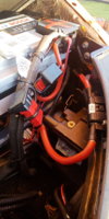
I used Anderson connectors at the interfaces of the batteries to allow quick disconnects.
IMG20191215141811.jpg
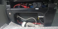
I have a 60A fuse as it leaves the engine bay, and a 100A fuse between the Redarc and the leisure battery (because I have the leisure battery connected to an inverter) if no inverter then a 60A there would do.
I fed a negative from starter to under the seat, but also connected an earth to the van under the seat as well, belt & braces I suppose.
IMG20191124141801.jpg
Used a couple of 3 way busbars for connecting all the positives and negatives together
12 / 24V 300A 3 Way / Pin Bus Bar Power Distribution Box Cable Connector Block | eBay
and some simple busbars to connect the redarc cables to the various inputs (alternator from engine bay and solar input) 48VDC Car Boat Electrical Double Type M8 Terminal Stud Bus Bar Red | eBay
 
Last edited:
Grim reaper,

Thanks again for so much input, which has provoked more questions :(

Whats the ampage of your Anderson connectors?
Did you use just one half of the Anderson connector for your live rather than live and negative?
Do you feel there is a benefit to connecting direct to the starter rather than negative on battery? And is this as hard as getting to the alternator? Which I understand means the front of the van coming off?!
I was considering fitting the redarc in a similar position to yours but on the removable board on the back of the seat as I have swivel bases that take some un-bolting. Did you consider this or even think it would work? Can you see the display panel whee you have installed yours?
Ref the live ignition feed, see attached screenshot from the Redarc instructions. I’m having trouble making sense of this 12v ON and 11.9v OFF. I understand the likes on my old split charger being Cut in 13.3v and Cut out 12.8v as this range makes more sense. Or is the case that because of the smart alternator Redarc have designed the BCDC1240D to literally switch to ON at ALMOST every given opportunity?
Am I right in saying I’ve read somewhere there is an ignition live under the passenger seat, or this perhaps only on the cali’s?
Did you set your profile to ‘A' max charge Voltage 14.6?
I see you have terminal covers on the starter battery. Do you have these on the leisure battery/batteries and any recommendations?
Good idea re the belt and braces earth:thumbsup:

Redarc.png
 
Anderson SB50 are rated to 120A
Sorry for misleading wording.. I meant the starter battery, although I have actually bolted the negative lead to an earth point right next to the battery rather than to the negative post of the battery itself, need to be sure only the van connection is on that terminal to retain the shunt workings. I have both pos & neg through the anderson connectors at starter & leisure batteries.
I took a live out of the fuse box under the dash, somewhere in the middle strip of fuses if I recall correctly.
I have a Lithium leisure battery, so I’m using the Li option, no need to look at the led’s I can see if the battery is charging from the Victron BMV712 display.
I couldn’t find a 12v live under the passenger seat on mine.
I bought a couple of terminal covers off ebay for the leisure battery BATTERY POST STARTER MOTOR TERMINAL COVER RED & BLACK CAR GOLF BUGGY MOBILITY | eBay
Or did you mean the anderson connectors? I have some spares (bought 10) if you want some let me know.
 
Many thanks again
I took a live out of the fuse box under the dash, somewhere in the middle strip of fuses if I recall correctly.
Do you know if there is a need to know the ampage or if any 12v feed is OK for this?

Or did you mean the anderson connectors? I have some spares (bought 10) if you want some let me know.
Thanks for the kind offer but my brother-in-law offered me some as a friend who once supplied them gave him loads when he went bust. Just wanted to check there’s no such thing as too high a rating but din’t think it would be the case, he has some 180a I think but mostly 120a.


Can I also ask about the 12v cig sockets behind the seat? Are they supplied directly from the leisure batteries and have you added any kind of surge protection (I think they call it) to protect vulnerable items plugged into them?
 
I installed a connector into a spare slot, just used a 1A fuse, it’s only a sense wire, no current draw to speak of.
The 12V sockets are fed from the fuse box off the leisure battery feed, just a 15A fuse, there shouldn’t be any surging going on, it’s just the same as the dash socket, so long as whatever you’re plugging into it is fused at the correct rating then that’s all that’s required.
 
I used a camlock/ cam buckle tie down strap, cut to suit and Riveted to the seat base.
 
Hello Grim Reaper,

Got my new shiny VCDS yesterday abut unfortauantly working away so can't get at it on the van yet.

I'm still buying bits for the leisure battery fit. Can I ask you if you used any kind of trays beneath the batteries under the seats and whether they are needed or not anyone?
 
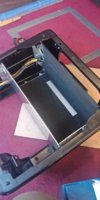
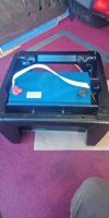
I made a box out of aluminium sheet to hold the battery. The Victron Superpack was a bit too high and yhe slider mechanism would have caught it so I added some rails either side to allow it to fit.

IMG20190428191415.jpg
IMG20190428191447.jpg
IMG20190422165822.jpg
 
I'm holding off on the VCDS for now as find it gets a bit absorbing and won't get away with it over the Xmas break :oops:

So I have started a little light removal work in the form of the front seats and will probably remove the bases as well for clearing as the last owner obviously doesn't like things as clean as I do!

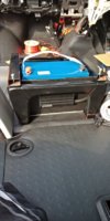
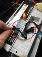
I was wondering if anybody knows what the connectors are in the ring in my photo below? I don't believe I have air bag/s in seat/s but may be wrong. Not sure if they would show but the seats have been re-covered and nothing visible on the outside. There is a corresponding socket under the seat.

Yes that is bodged up duct tape - added by last owner - acting as a terminal cover :eek:

Thanks in advance.

Connectors.jpeg
 
probably the link to the switch built into the seat that tells the van someone is sitting in the seat
 
Grim reaper,

Did you use fuse way 19 for your ignition live as per this doc > https://8f5d4f75-0e78-4b9a-99dd-bb2...d/d959f6_4e84b63f4383484ea1097894b235b0fe.pdf

if so (or even if you used a different one) is there a way to make this connection without using a fuse blade (jumper)? can the connection come off the back somewhere to look tidier?

Thanks for the heads up on the socket under seat.

Thanks.

EDIT: Forgot to say, almost related, when you strip the dash back does removing the end (passenger side) as per top of page 2 in doc above and unplugging the air bag on/off cause a fault?
 
If you disassemble the van to the point where you can get the fuse box unbolted (be wary of dropping bolts down the gap) you can remove the black plastic cover that covers the wire entries to the rear of the box, then remove the purple plastic combs that lock the wires that are already in place.
There are several empty fuse positions assosiated with each part of the fuse box, by using a multimeter you can tell which parts are live all the time and which parts come live with ignition.
I used a Power Timer contact and inserted it (with a wire attached) into the spare port of one of the 'switched' spare ports.
If I remember correctly, JPT terminals fit the small ATM/Mini fuses, SPT terminals fit the larger ATO/Standard ones.
8x 927781-3 Contact female 1÷2.5mm2 JPT tinned crimped for cable 7426041499406 | eBay
20x 927833-1/C Contact female 1÷2.5mm2 SPT tinned crimped cut from reel 7431906486460 | eBay
Once the terminal is inserted (the correct way round) reinsert the purple comb to lock it in place, replace the cover that slides over the back and return the fuse box to its position and bolt it back in.
You will only get a DTC if you turn the ignition on whilst the switch is out of circuit, but, if yopu have VCDS it's a simple matter to clear any codes if they turn up.
 
Thanks Grim Reaper
If you disassemble the van to the point where you can get the fuse box unbolted (be wary of dropping bolts down the gap) you can remove the black plastic cover that covers the wire entries to the rear of the box, then remove the purple plastic combs that lock the wires that are already in place.
There are several empty fuse positions assosiated with each part of the fuse box, by using a multimeter you can tell which parts are live all the time and which parts come live with ignition.
I used a Power Timer contact and inserted it (with a wire attached) into the spare port of one of the 'switched' spare ports.
If I remember correctly, JPT terminals fit the small ATM/Mini fuses, SPT terminals fit the larger ATO/Standard ones.
8x 927781-3 Contact female 1÷2.5mm2 JPT tinned crimped for cable 7426041499406 | eBay
20x 927833-1/C Contact female 1÷2.5mm2 SPT tinned crimped cut from reel 7431906486460 | eBay
Once the terminal is inserted (the correct way round) reinsert the purple comb to lock it in place, replace the cover that slides over the back and return the fuse box to its position and bolt it back in.
You will only get a DTC if you turn the ignition on whilst the switch is out of circuit, but, if yopu have VCDS it's a simple matter to clear any codes if they turn up.
I understand this
If you are using one of these 2 x Add A Circuit Piggy Back Fuse Tap Standard Blade Fuse Holder ATO 12V UK | eBay just pick a small fuse in the 'switched' part of the box.
But if I do as per your post above what purpose will the the piggy back connection have?
 
Back
Top